

Top
Author
Published
10 Nov 2026Form Number
LP2495PDF size
68 pages, 13.3 MBSubscribed to LP2495.
Thank you for your feedback.
Table of Contents
- Introduction
- Did you know?
- Key features
- Performance benchmarks
- Components and connectors
- System architecture
- Standard specifications - SC755 V5 tray
- Standard specifications - N1380 enclosure
- Models
- Processors
- Memory
- GPU accelerators
- Internal storage
- Controllers for internal storage
- Internal drive options
- I/O expansion
- Network adapters
- Cooling
- Water connections
- Power conversion stations
- System Management
- Security
- Operating system support
- Physical and electrical specifications
- Operating environment
- Regulatory compliance
- Warranty upgrades and post-warranty support
- Services
- Lenovo TruScale
- Rack cabinets
- Genie Material Lift
- Lenovo Financial Services
- Seller training courses
- Related publications and links
- Related product families
- Trademarks
Abstract
The ThinkSystem SC755 V5 Neptune server is a high-performance server based on the 7th generation Lenovo Neptune® direct water cooling platform. With AMD EPYC 9006 Series SP7 Server CPUs, the ThinkSystem SC755 V5 server combines the latest high-performance AMD "Venice" processors and Lenovo's market-leading water-cooling solution, which results in extreme performance in dense packaging.
This product guide provides essential pre-sales information to understand the SC755 V5 server, its key features and specifications, components and options, and configuration guidelines. This guide is intended for technical specialists, sales specialists, sales engineers, IT architects, and other IT professionals who want to learn more about the SC755 V5 and consider its use in IT solutions.
Introduction
The ThinkSystem SC755 V5 Neptune node is a high-performance server based on the 7th generation Lenovo Neptune® direct water cooling platform. Each SC755 V5 tray contains two 2-socket nodes, and 8 trays are housed in the ThinkSystem N1380 enclosure, a 13U rack mount unit that fits in a standard 19-inch rack.
With 6th Generation AMD EPYC 9006 Series SP7 Server CPUs, the ThinkSystem SC755 V5 server combines the latest high-performance AMD "Venice" processors and Lenovo's market-leading water-cooling solution, which results in extreme performance in dense packaging. This 100% direct water cooled solution is designed to operate by using warm water, up to 45°C (113°F).
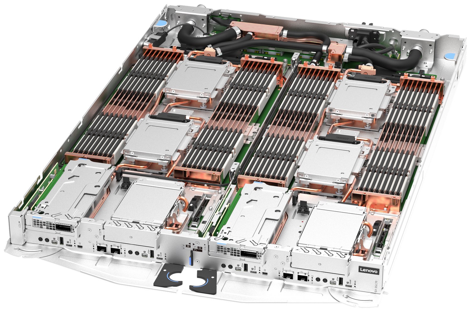
Figure 1. The Lenovo ThinkSystem SC755 V5 server tray with two distinct two-socket nodes
Did you know?
The ThinkSystem SC755 V5 can be ordered as a tray with 2 separate nodes, each with 2 processors, or it can be ordered 4 separate nodes, each with 1 processor. Each node has its own XCC4 service processor. This flexibility ensures that the server is configured to best suit your intended workload. For example, workloads such as astrophysics, that can take advantage of more cores and more memory, the SC755 V5 can be ordered as 2 nodes per tray, each with 2 CPUs and 4TB of memory. However, if you run workloads such as genomics, where you need more systems with fewer cores and less memory, the SC755 V5 can be configured as 4 nodes per tray, each with a single CPU and 2TB of memory. This flexibility means your compute resources can better match the needs of your business to maximize your return on investment.
Key features
The ThinkSystem SC755 V5 builds on the proven infrastructure established with the SC750 V4, using the same ThinkSystem N1380 Neptune enclosure and vertically mounted, direct water-cooled server tray design. This common infrastructure enables customers to deploy the latest AMD EPYC 9006 Series SP7 Server CPUs while maintaining a consistent chassis, cooling, power, and rack-level infrastructure across system generations.
Lenovo Dynamic Partitioning
The SC755 V5 further introduces Lenovo Dynamic Partitioning™, a flexible compute architecture that enables customers to be able to configure the server in a way that best suits their workload requirements.
Each tray contains four AMD EPYC 9006 Series SP7 Server CPUs and 64 DIMM slots, and each tray can be configured in two ways:
- Two independent 2-socket nodes (2N2S) with 32 DIMMs per node for greater compute and memory resources per node, or
- Four independent 1-socket nodes (4N1S) with 16 DIMMs per node for greater node density and finer-grained compute resources for scale-out workloads
The combination of common infrastructure and flexible node topology enables customers to optimize the compute architecture for different HPC and AI workloads while using the same SC755 V5 platform.
Agentic AI Execution Layer
The SC755 V5 server provides the CPU, memory, and orchestration infrastructure required to execute multi-agent AI workflows at scale. Rather than focusing on model training, the platform is designed to host agent runtimes, tool execution services, retrieval pipelines, and enterprise orchestration frameworks.
Key workload domains:
- Agent runtime and orchestration services
- Retrieval and knowledge processing pipelines
- CPU-based tool execution
- Distributed agent execution environments
- AI for Science and simulation workflows
The SC755 V5 server combines high core density, large memory capacity, high-speed interconnects, and Neptune direct water cooling to support large-scale agent execution infrastructures.
Revolutionary Lenovo Neptune Design
Engineered for large-scale cloud infrastructures and High Performance Computing (HPC), Lenovo ThinkSystem SC755 V5 Neptune excels in intensive simulations and complex modeling. It is designed to handle technical computing, grid deployments, and analytics workloads in various fields such as research, life sciences, energy, engineering, and financial simulation.
At its core, Lenovo Neptune applies 100% direct warm-water cooling, maximizing performance and energy efficiency without sacrificing accessibility or serviceability. The SC755 V5 integrates seamlessly into a standard 19-inch rack cabinet with the ThinkSystem N1380 Neptune enclosure, featuring a patented blind-mate stainless steel dripless quick connection.
This design ensures easy serviceability and extreme performance density, making the SC755 V5 the go-to choice for compute clusters of all sizes - from departmental/workgroup levels to the world’s most powerful supercomputers – from Exascale to Everyscale®.
Lenovo Neptune utilizes superior materials, including custom copper water loops and patented CPU cold plates, for full system water-cooling. Unlike systems that use low-quality FEP plastic, Neptune features durable stainless steel and reliable EPDM hoses. The N1380 enclosure features an integrated manifold that offers a patented blind-mate mechanism with aerospace-grade drip-less connectors to the compute trays, ensuring safe and seamless operation.
Compared to an equivalent air-cooled system, the SC755 V5 provides:
- Up to 40% data center energy use reduction from server and infrastructure
- Up to 100% heat removal by water directly on the heat sources
- Up to 100% noise reduction by server fans in the data center
Lenovo’s direct water-cooled solutions are factory-integrated and are re-tested at the rack-level to ensure that a rack can be directly deployed at the customer site. This careful and consistent quality testing has been developed as a result of over a decade of experience designing and deploying DWC solutions to the very highest standards.
Scalability and performance
The ThinkSystem SC755 V5 server tray and ThinkSystem N1380 enclosure offer the following features to boost performance, improve scalability, and reduce costs:
- Each SC755 V5 node supports two AMD EPYC 9006 Series SP7 Server CPUs, codenamed "Venice", 32x TruDDR5 RDIMMs, up to two PCIe 6.0 slots for high-speed I/O, and up to two drive bays.
- 16x SC755 V5 dual-socket nodes are mounted in 8x trays which are installed vertically in the 13U N1380 enclosure. With server nodes effectively occupying less than 1U of rack space, it is a dense, scalable, and high performance offering.
- The SC755 V5 supports multiple compute and networking topologies within a common platform design, enabling customers to optimize infrastructure for different workloads requirements.
- The SC755 V5 can be configured as either 2 nodes, each with 2 processor sockets (2N2S), optimized for workloads requiring higher per node performance and larger memory capacity; or 4 nodes, each with 1 socket (4N1S), optimized for scale-out environments that benefit from higher node density and finer resource granularity.
- When the nodes are configured as 2-socket nodes, each node supports two processors, 32x TruDDR5 RDIMMs or MRDIMMs, up to two PCIe 6.0 slots for high-speed I/O, and up to six E3.S 1T drive bays.
- When the nodes are configured as 1-socket nodes, each node has one processor, 16x TruDDR5 RDIMMs or MRDIMMs, one PCIe 6.0 slot, and up to three E3.S 1T drive bays.
- Supported AMD EPYC 9006 Series SP7 Server CPUs have:
- Up to 256 cores and 512 threads
- Maximum boost frequencies up to 5.3GHz
- TDP ratings up to 600W
- Support for DDR5 memory DIMMs to maximize the performance of the memory subsystem. Each node supports the following:
- Up to 32 DDR5 memory DIMMs with 2 processors (16 DIMMs per processor)
- 16 memory channels per processor (1 DIMM per channel)
- Support for RDIMMs (operating at 8000 MT/s) and MRDIMMs (operating at 12800 MT/s)
- In a 2-socket node configuration and using 32x 128GB RDIMMs, the each node supports up to 4TB of system memory
- When configured as 2-socket nodes, each node has two front bays that support either a PCIe adapter or E3.S drives, giving the following choices:
- 2x PCIe 6.0 x16 slots
- 1x PCIe slot plus 2x E3.S 1T drives
- 4x E3.S 1T drives
- In addition, each node supports 2x E3.S 1T drives mounted on cold plates on top of the two processors
- All supported drives are E3.S NVMe drives, to maximize I/O performance in terms of throughput, bandwidth, and latency.
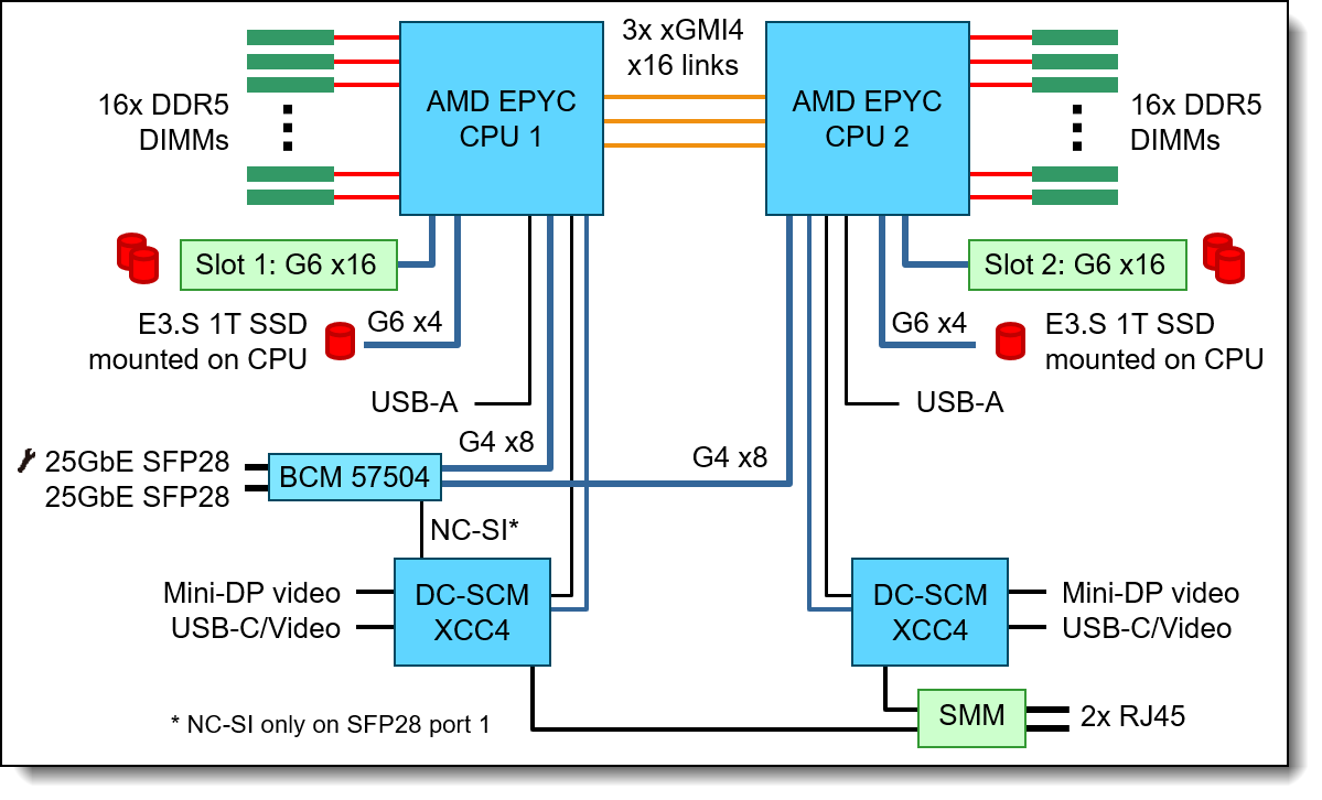
- Each 2-socket node includes two 25 Gb Ethernet onboard ports for cost effective networking. High speed networking can be added through the included PCIe slots. Port 1 of the 25Gb ports supports NC-SI for BMC management communication to the BMC in addition to the host communication.
- The node offers PCI Express 6.0 I/O expansion capabilities that doubles the theoretical maximum bandwidth of PCIe 5.0 (64GT/s in each direction for PCIe 6.0, compared to 32 GT/s with PCIe 5.0). A PCIe 6.0 x16 slot provides 256 GB/s bandwidth, enough to support a 800GbE network connection.
Energy efficiency
The direct water cooled solution offers the following energy efficiency features to save energy, reduce operational costs, increase energy availability, and contribute to a green environment:
- Water cooling eliminates power that is drawn by cooling fans in the enclosure and dramatically reduces the required air movement in the server room, which also saves power. In combination with an Energy Aware Runtime environment, savings as much as 40% are possible in the data center due to the reduced need for air conditioning.
- Water chillers may not be required with a direct water-cooled solution. Chillers are a major expense for most geographies and can be reduced or even eliminated because the water temperature can now be 45°C instead of 18°C in an air-cooled environment.
- With the new water-cooled power conversion stations and SMM3, essentially 100% system heat recovery is possible, depending on water and ambient temperature chosen. At 45°C water temperature and 30°C room temperature, it will typically be around 95% through surface radiated heat. Heat energy absorbed may be reused for heating buildings in the winter, or generating cold through Adsorption Chillers, for further operating expense savings.
- The processors and other microelectronics run at lower temperatures because they are water-cooled, which uses less power, and allows for higher performance through Turbo Mode.
- The processors are run at uniform temperatures because they are cooled in parallel loops, which avoid thermal jitter and provides higher and more reliable performance at same power.
- Low-voltage 1.1V DDR5 memory offers energy savings compared to 1.2V DDR4 DIMMs, an approximately 20% decrease in power consumption
- 80 PLUS Titanium-compliant power conversion stations ensure energy efficiency.
- Power monitoring and management capabilities through the System Management Module in the N1380 enclosure.
- The System Management Module (SMM3) automatically calculates the power boundaries at the enclosure level; the protective capping feature ensures overall power consumption stays within limits, adjusting dynamically based on the server and power conversion station status change.
- Lenovo power/energy meter based on TI INA228 measures DC power for the CPU at higher than 97% accuracy and 100 Hz sampling frequency to the XCC and can be leveraged both in-band and out-of-band using IPMI raw commands.
- Optional Lenovo XClarity Energy Manager provides advanced data center power notification, analysis, and policy-based management to help achieve lower heat output and reduced cooling needs.
- Optional Energy Aware Runtime provides sophisticated power monitoring and energy optimization on a job-level during the application runtime without impacting performance negatively.
Manageability and security
The following powerful systems management features simplify local and remote management of the SC755 V5 server:
- Each node includes an XClarity Controller 4 (XCC4) on a DC-SCM module to monitor server availability. Each server tray has 2x or 4x DC-SCM modules (1 per node), depending on the tray configuration. Optional upgrade to XCC4 Premier to provide remote control (keyboard video mouse) functions, support for the mounting of remote media files, FIPS 140-3 security, enhanced NIST 800-193 support, boot capture, power capping, and other management and security features.
- Lenovo XClarity One offers comprehensive hardware management tools that help to increase uptime, reduce costs, and improve productivity through advanced server management capabilities.
- Lenovo XClarity Provisioning Manager, based in UEFI and accessible from F1 during boot, provides system inventory information, graphical UEFI Setup, platform update function, RAID Setup wizard, operating system installation function, and diagnostic functions.
- Support for Lenovo XClarity Energy Manager which captures real-time power and temperature data from the server and provides automated controls to lower energy costs.
- Support for industry standard management protocols, IPMI 2.0, SNMP 3.0, Redfish REST API, serial console via IPMI
- The SC755 V5 is enabled with Lenovo HPC & AI Software Stack, so, you can support multiple users and scale within a single cluster environment.
- Lenovo HPC & AI Software Stack provides our HPC customers with a fully tested and supported open-source software stack to enable your administrators and users with the most effective and environmentally sustainable consumption of Lenovo supercomputing capabilities.
- Our Confluent management system provides an interface designed to abstract the users from the complexity of HPC cluster orchestration and AI workloads management, making open-source HPC software consumable for every customer.
- Integrated Trusted Platform Module (TPM) 2.0 support enables advanced cryptographic functionality, such as digital signatures and remote attestation.
- Supports Secure Boot to ensure only a digitally signed operating system can be used.
- Industry-standard Advanced Encryption Standard (AES) NI support for faster, stronger encryption.
- With the System Management Module (SMM) installed in the enclosure, only one Ethernet connection is needed to provide remote systems management functions for all SC755 V5 servers and the enclosure.
- The SMM3 management module has two Ethernet ports which allows a single Ethernet connection to be daisy chained, up to 99 connections (eg 3 enclosures and 96 servers), thereby significantly reducing the number of Ethernet switch ports needed to manage an entire rack of SC755 V5 servers and N1380 enclosures.
- The N1380 enclosure and its power conversion stations include drip sensors that monitor the inlet and outlet manifold quick connect couplers; leaks are reported via the SMM.
Availability and serviceability
The SC755 V5 node and N1380 enclosure provide the following features to simplify serviceability and increase system uptime:
- Designed to run 24 hours a day, 7 days a week
- With full water cooling, system fans are not required. This results in significantly reduced noise levels on the data center floor, a significant benefit to personnel having to work on site.
- Depending on the configuration and node population, the N1380 enclosure supports N+1 or N+N power policies for its power conversion stations, which means greater system uptime.
- Power conversion stations are hot-swappable to minimize downtime.
- Toolless cover removal on the trays provides easy access to upgrades and serviceable parts, such as adapters and memory.
- The server uses ECC memory and supports memory RAS features including Single Device Data Correction (SDDC, also known as Chipkill), Patrol/Demand Scrubbing, Bounded Fault, DRAM Address Command Parity with Replay, DRAM Uncorrected ECC Error Retry, On-die ECC, ECC Error Check and Scrub (ECS), and Post Package Repair.
- Proactive Platform Alerts (including PFA and SMART alerts): Processors, voltage regulators, memory, internal storage, fans, power conversion stations, and server ambient and subcomponent temperatures. Alerts can be surfaced through the XClarity Controller to managers such as Lenovo XClarity Administrator and other standards-based management applications. These proactive alerts let you take appropriate actions in advance of possible failure, thereby increasing server uptime and application availability.
- The XCC offers optional remote management capability and can enable remote keyboard, video, and mouse (KVM) control and remote media for the node.
- Built-in diagnostics in UEFI, using Lenovo XClarity Provisioning Manager, speed up troubleshooting tasks to reduce service time.
- Lenovo XClarity Provisioning Manager supports diagnostics and can save service data to a USB key drive or remote CIFS share folder for troubleshooting and reduce service time.
- Auto restart in the event of a momentary loss of AC power (based on power policy setting in the XClarity Controller service processor)
- Virtual reseat is a supported feature of the System Management Module which, in essence, removes the node from A/C power and reconnecting the node to AC power from a remote location.
- There is a three-year customer replaceable unit and onsite limited warranty, with next business day 9x5 coverage. Optional warranty upgrades and extensions are available.
Performance benchmarks
At Lenovo, we know customers care most about how their workloads perform in real-world environments, which is why we carefully tune our server hardware, firmware, and drivers to help deliver strong benchmark results that reflect practical business needs. The goal is simple: to help customers run their critical applications more efficiently and achieve better outcomes.
Lenovo performance engineers have achieved world record performance benchmarks on many ThinkSystem servers. See the complete list of current world records in the Lenovo Press article Performance Benchmark World Record Summary for Lenovo ThinkSystem Servers.
The Lenovo Server Performance Team also publishes reports on key performance world records at the time the world record is announced. See all published Performance Benchmark Reports.
Components and connectors
The front of the tray with two distinct SC755 V5 nodes is shown in the following figure.
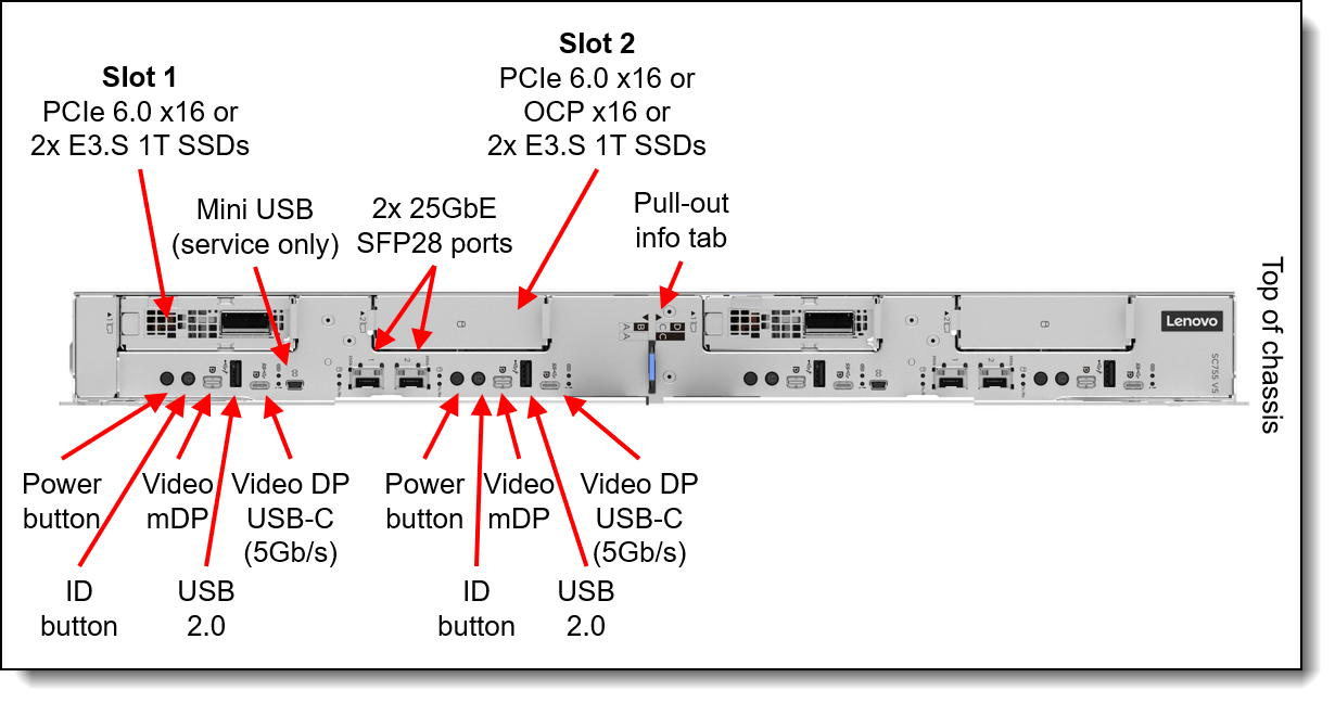
Figure 2. Front view of the tray with two ThinkSystem SC755 V5 nodes
The following figure shows the top-down view of the 2-node configuration. Each node has 2 processors and 2 PCIe slots.
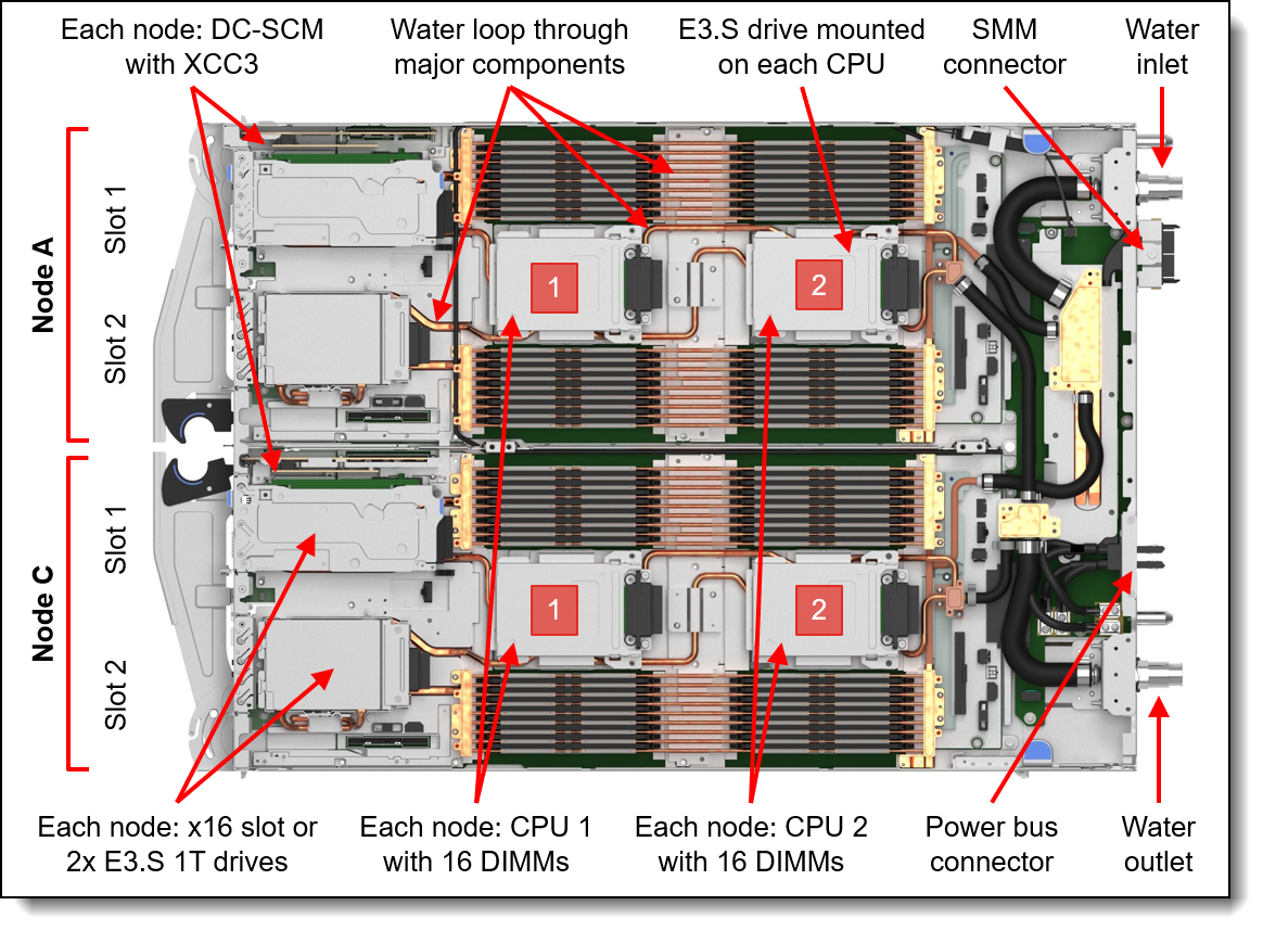
Figure 3. Top-down view of the two-node configuration
The following figure shows the top-down view of the 4-node configuration. Each node has 1 processor and 1 PCIe slot.
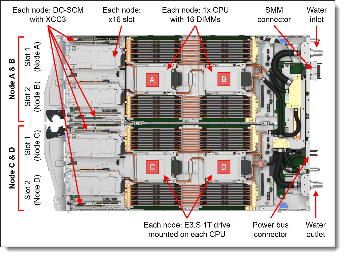
Figure 4. Top-down view of the four-node configuration
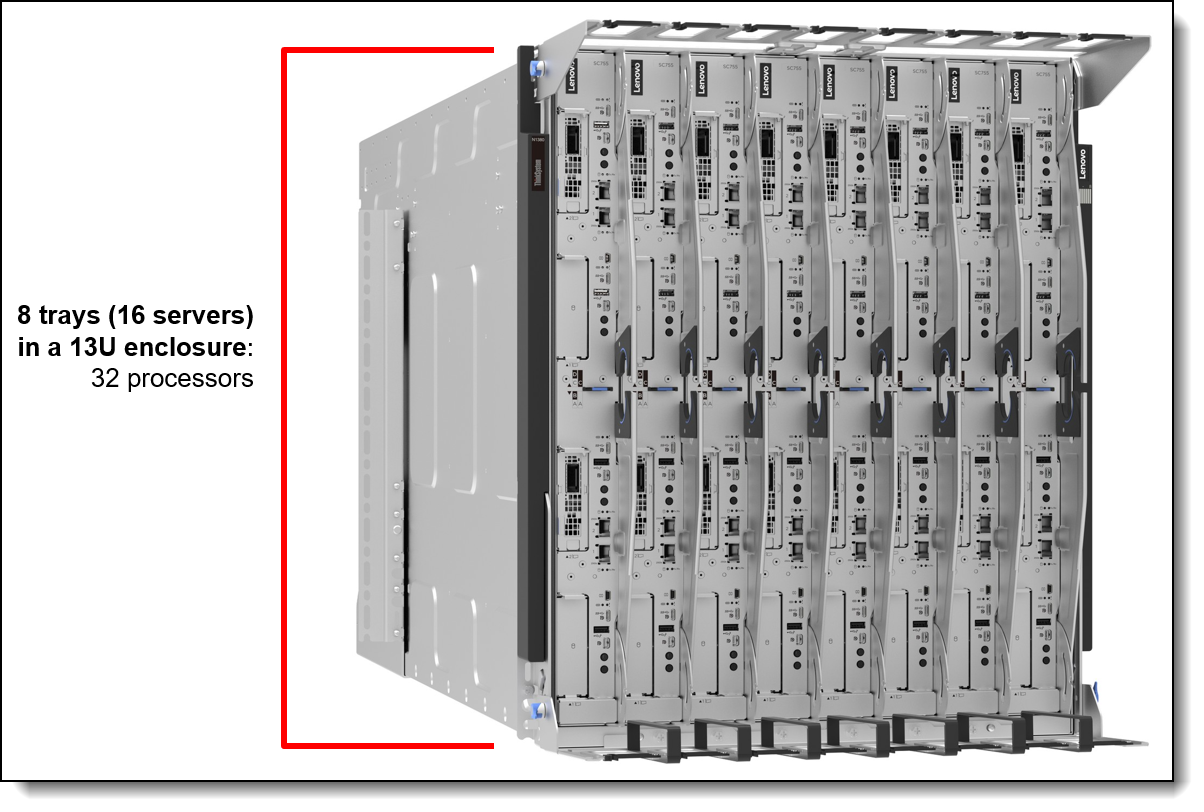
The compute nodes are installed vertically in the ThinkSystem N1380 enclosure, as shown in the following figure.
The rear of the N1380 enclosure contains the 4x water-cooled power conversion stations (PCS), water connections, and the System Management Module.
Note: The short hoses that are attached to the water inlet and water outlet have been removed from the figure for clarity.

Figure 6. Rear view of the N1380 enclosure (water hoses removed for clarity)
Standard specifications - SC755 V5 tray
The following table lists the standard specifications of the SC755 V5 server tray.
| Components | Specification |
|---|---|
| Machine type | 7DN6 - 3-year warranty |
| Form factor | Two independent 2-socket nodes mounted on a water-cooled server tray, installed vertically in an enclosure |
| Enclosure support |
ThinkSystem N1380 enclosure |
| Processor |
Each 2-socket node: Two AMD EPYC 9006 Series SP7 Server CPUs (formerly codenamed "Venice") per node. Supports processors up to 256 cores, core speeds of up to 4.1 GHz, and TDP ratings of up to 600W. Supports PCIe 6.0 for high performance connectivity to network adapters and NVMe drives. |
| Chipset | None. Integrated into the processor. |
| Memory | Each 2-socket node: 32 DIMM slots with two processors (16 DIMM slots per processor) per node. Each processor has 16 memory channels, with 1 DIMM per channel (DPC). Supports Lenovo TruDDR5 RDIMMs at 8000 MT/s and MRDIMMs at 12800 MT/s. |
| Memory maximum | Up to 4TB per 2-socket node with 32x 128GB RDIMMs |
| Memory protection | ECC, SDDC (for x4-based memory DIMMs), Patrol/Demand Scrubbing, Bounded Fault, DRAM Address Command Parity with Replay, DRAM Uncorrected ECC Error Retry, On-die ECC, ECC Error Check and Scrub (ECS), Post Package Repair |
| Disk drive bays |
Each 2-socket node supports up to 6x EDSFF E3.S 1T NVMe SSDs:
|
| Maximum internal storage | 184.32TB using 6x 30.72TB E3.S NVMe SSDs |
| Storage controllers |
Onboard NVMe ports (OS-based RAID only) |
| Network interfaces | Each 2-socket node: 2x 25 Gb Ethernet SFP28 onboard connectors based on Broadcom 57504 controller (support 10/25Gb), Onboard 25Gb port 1 can optionally be shared with the XClarity Controller 4 (XCC4) management processor for Wake-on-LAN and NC-SI support. |
| PCIe slots | Each two-socket node: 1x or 2x PCIe 6.0 x16 slots with low profile form factor (each slot is mutually exclusive with E3.S drives installed in that bay) |
| GPUs | No support. |
| Ports | USB-C for USB data or DisplayPort video port, 2x USB 3 (5 Gb/s) ports, 2x mini DP, mini-USB serial port. Additional ports provided by the enclosure as described in the Enclosure specifications section. |
| Video | Embedded graphics with 16 MB memory with 2D hardware accelerator, integrated into the XClarity Controller 4 management controller. Two video ports (Mini-DisplayPort video port or USB-C DisplayPort video port; cannot be used simultaneously). Maximum resolution is 1920x1200 32bpp at 60Hz. |
| Security features | Power-on password, administrator's password, Trusted Platform Module (TPM), supporting TPM 2.0. In China only, optional Nationz TPM 2.0 plug-in module, 1 per node. |
| Systems management |
Up to 4x DC-SCM modules per SC755 V5 tray, one DC-SCM for each node. Each DC-SCM contains the XClarity Controller 4 (XCC4) based on the ASPEED AST2700 baseboard management controller (BMC). Support for XClarity One centralized infrastructure management and XClarity Energy Manager centralized server power management. Optional XCC4 Premier to enable remote control functions and other features. Lenovo power/energy meter based on TI INA228 for 100Hz power measurements with >97% accuracy. Status LEDs on the front of the server. System Management Module (SMM3) in the N1380 enclosure provides additional systems management functions from power monitoring to liquid leakage detection on chassis, tray and power conversation station level. |
| Operating systems supported |
Red Hat Enterprise Linux, SUSE Linux Enterprise Server, and Ubuntu are Supported & Certified. Rocky Linux and AlmaLinux are Tested. See the Operating system support section for details and specific versions. |
| Limited warranty | Three-year customer-replaceable unit and onsite limited warranty with 9x5 next business day (NBD). |
| Service and support | Optional service upgrades are available through Lenovo Services: 4-hour or 2-hour response time, 6-hour fix time, 1-year or 2-year warranty extension, software support for Lenovo hardware and some third-party applications. |
| Dimensions | Width: 546 mm (21.5 inches), height: 53 mm (2.1 inches), depth: 760 mm (29.9 inches) |
| Weight | 36.5 kg (80.5 lb) |
Standard specifications - N1380 enclosure
The ThinkSystem N1380 enclosure provides shared high-power and high-efficiency power conversion stations. The SC755 V5 servers connect to the midplane of the N1380 enclosure. This midplane connection is for power (via a 48V busbar) and control only; the midplane does not provide any I/O connectivity.
The following table lists the standard specifications of the enclosure.
| Components | Specification |
|---|---|
| Machine type | 7DDH - 3-year warranty |
| Form factor | 13U rack-mounted enclosure |
| Maximum number of SC755 V5 nodes supported | Up to 16x 2-socket nodes per enclosure in 8x SC755 V5 server trays (2 nodes per tray) |
| Node support | ThinkSystem SC750 V4 ThinkSystem SC777 V4 ThinkSystem SC755 V5 |
| Enclosures per rack | Up to three N1380 enclosures per 42U or 48U rack |
| System Management Module (SMM) |
The hot-swappable System Management Module (SMM3) is the management device for the enclosure. Provides integrated systems management functions and controls the power and cooling features of the enclosure. Provides remote browser and CLI-based user interfaces for remote access via the dedicated Gigabit Ethernet port. Remote access is to both the management functions of the enclosure as well as the XClarity Controller 4 (XCC4) in each node. The SMM has two Ethernet ports which enables a single incoming Ethernet connection to be daisy chained across 3 enclosures and 48 nodes, thereby significantly reducing the number of Ethernet switch ports needed to manage an entire rack of SC755 V5 nodes and enclosures. |
| Ports | Two RJ45 port on the rear of the enclosure for 10/100/1000 Ethernet connectivity to the SMM3 for power and cooling management. |
| I/O architecture | None integrated. Use top-of-rack networking and storage switches. |
| Power supplies | Up to 4x water-cooled hot-swap power conversion stations (PCS), depending on the power policy and the power requirements of the installed server node trays. Optional redundancy (N+1 or N+N) and oversubscription, depending on configuration and node population. PCS units are installed at the rear of the enclosure. Single power domain supplies power to all nodes. 80 PLUS Titanium compliant. Built-in overload and surge protection. |
| Cooling | Direct water cooling supplied by water hoses connected to the rear of the enclosure. |
| System LEDs | SMM has four LEDs: system error, identification, status, and system power. Each power conversion station (PCS) has AC, DC, and error LEDs. Nodes have more LEDs. |
| Systems management | Browser-based enclosure management through an Ethernet port on the SMM at the rear of the enclosure. Integrated Ethernet switch provides direct access to the XClarity Controller (XCC) embedded management of the installed nodes. Nodes provide more management features. |
| Temperature |
See Operating Environment for more information. * ASHRAE S45, formerly known as ASHRAE W45 |
| Electrical power | 380~480Vac, 3-phase WYE |
| Power cords | Custom power cables for direct data center attachment, 1 dedicated (32A) or 1 shared (63A) per power module |
| Limited warranty | Three-year customer-replaceable unit and onsite limited warranty with 9x5/NBD. |
| Dimensions | Width: 540 mm (21.3 in.), height: 572 mm (22.5 in.), depth: 1302 mm (51.2 in.). See Physical and electrical specifications for details. |
| Weight |
|
Models
The SC755 V5 node and N1380 enclosure are configured by using the configure-to-order (CTO) process with the Lenovo Cluster Solutions configurator (x-config) or in Lenovo Data Center Solution Configurator (DCSC).
DCSC users: To configure SC755 V5 and N1380 in DCSC, you will need to be in AI & HPC – ThinkSystem Hardware mode. General Purpose mode cannot be used to configure these systems.
The following table lists the base CTO models and base feature codes.
The choice of base configuration determines how the server is configured in the factory. The selections are as follows:
- Base feature CCKT - The SC755 V5 tray is configured as two independent nodes (Nodes A & C), each with
- 2x processors
- 32x memory DIMMs
- 2x PCIe slots (or 4x E3.S 1T drive bays)
- Base feature CCKU - The SC755 V5 tray is configured as four independent nodes (Nodes A, B, C, D), each with:
- 1x processor
- 16x memory DIMMs
- 1x PCIe slot (or 2x E3.S 1T drive bays)
The following figure shows the 2-node configuration (CCKT). The left half of the tray is Node A and the right half of the tray is Node C.
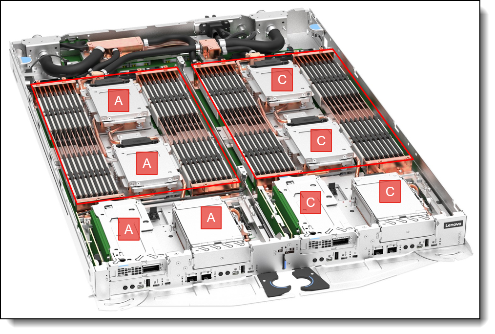
Figure 8. SC755 V5 tray configured as 2 nodes
The following figure shows the 4-node configuration. As you can see in the labels, each node (A, B, C, and D) has a single processor and adjacent memory plus one of the slots at the front of the tray. Each node can have its own network adapter, or two nodes can share a single network connection with the use of a Shared I/O cable.
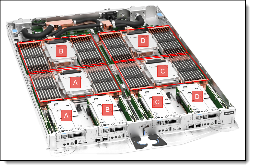
Figure 9. SC755 V5 tray configured as 4 nodes
Reconfiguring the SC755 V5: With Lenovo Dynamic Partitioning, the SC755 V5 is designed to allow the administrator to reconfigure the server between 2N2S and 4N1S configurations. Such functionality is planned to be supported by using Lenovo Confluent. Each node will require a DC-SCM module as described in the DC-SCM module section.
Processors
The SC755 V5 is designed with a flexible compute architecture that supports two different node configurations within the same server tray, allowing customers to optimize the system for either per-node performance or greater scale-out density.
Each SC755 V5 tray supports four AMD EPYC 9006 Series SP7 Server CPUs (formerly codenamed "Venice SP7") and can be configured as:
- 2-node, 2-socket (2N2S): Two independent compute nodes, each with two processors. This configuration is optimized for workloads that benefit from higher per-node compute performance and larger memory capacity. Each node supports up to 32 TruDDR5 DIMMs and two PCIe 6. Slots.
- 4-node, 1-socket (4N1): Four independent compute nodes, each with on processor. This configuration is optimized for scale-out workloads, providing greater node density and finer compute-resource granularity. Each node supports up to 16 TruDDR5 DIMMs and one PCIe 6.0 slot.
This Flexible architecture enables customers to right-size the compute topology for their workload, choosing greater resources per node with 2N2S or greater node-level scalability with 4N1S, while using the same SC755 V5 platform. Internal positioning specifically describes this as supporting both scale-up and scale-out execution from a common platform.
Supported processors offer up to 256 cores, core speeds up to 4.1 GHz, and TDP ratings up to 600W, with PCIe 6.0 connectivity.
.
Note: Four processors per SC755 V5 tray are required; other processor quantities are not supported.
Topics in this section:
Processor options
The following table lists the AMD EPYC 9006 Series SP7 Server CPUs that are supported by the SC755 V5.
Configuration rules:
- DCSC users: In the DCSC configurator, the SC755 V5 is listed as having 4 processors and 64 memory DIMM slots. That is because DCSC configures the entire tray at once, and the tray is comprised of 2 or 4 separate nodes.
- Controlled CPUs: As shown in the table, some processors are Controlled which means the processor is not offered in certain markets, as determined by the US Government. For more information, contact your sales representative.
Processor features
The following table summarizes the key features of the processors that are supported in the SC755 V5.
UEFI operating modes
The SC755 V5 offers preset operating modes that affect energy consumption and performance. These modes are a collection of predefined low-level UEFI settings that simplify the task of tuning the server to suit your business and workload requirements.
The following table lists the feature codes that allow you to specify the mode you wish to preset in the factory for CTO orders.
The preset modes for the SC755 V5 are as follows:
- ThinkSystem General Computing - Power Efficiency (feature C3JB): This workload profile optimizes the performance per watt efficiency with a bias towards performance. This workload profile is analogous to “Efficiency – Favor Performance” operating mode on ThinkSystem V3 servers. This profile contains settings for ENERGY STAR® and ERP Lot9 compliance.
- ThinkSystem General Computing - Peak Frequency (feature C3JA): This workload profile is defined by the requirement to drive the highest core frequencies out of a processor across a subset of cores available – not for all cores active. This workload profile benefits workloads requiring either high per core and / or overall CPU package frequency. These workloads may have variable resource demands, are relatively insensitive to overall platform latency, and are generally CPU clock constrained. Tuning a system for highest possible core frequency may mean allowing inactive cores to transfer in and out of sleep states (C-states), which allows active cores to run at higher frequency for different durations of time. Allowing cores to go into low power states allows for higher per core frequency but can introduce “jitter” in the systems clock frequency.
- ThinkSystem General Computing - Max Performance (feature C3J9): This workload profile maximizes the absolute performance of the system without regard for power savings. Power savings features are disabled. This operating mode should be used when an application can sustain work across all cores simultaneously and is Non-uniform Memory Access (NUMA) aware.
- ThinkSystem High Performance Computing (HPC) (feature C3J8): This profile is for customers running large-scale scientific and engineering workloads. These environments tend to be clustered environments where each node performs at maximum utilization for extended periods of time, and the application is Non-Uniform Memory Access (NUMA) aware.
Memory
The SC755 V5 uses Lenovo TruDDR5 RDIMM memory operating at 8000 MT/s or MRDIMM memory operating at 12800 MT/s (12.8 GT/s). The processors have 16 memory channels and support 1 DIMM per channel (DPC).
The SC755 V5 configured as nodes with two processors, supports 4TB of memory using 32x 128GB RDIMMs or 32x 128GB MRDIMMs.
Lenovo TruDDR5 memory uses the highest quality components that are sourced from Tier 1 DRAM suppliers and only memory that meets the strict requirements of Lenovo is selected. It is compatibility tested and tuned to maximize performance and reliability. From a service and support standpoint, Lenovo TruDDR5 memory automatically assumes the system warranty, and Lenovo provides service and support worldwide.
Note to DCSC users: In the DCSC configurator, the SC755 V5 is listed as having 4 processors and 64 memory DIMM slots. That is because DCSC configures the entire tray at once.
The following table lists the memory options that are supported.
The following rules apply when selecting the memory configuration:
- Mixing of DIMMs is not supported; all DIMMs must the same part numbers
-
The standard memory configuration populates all 16 memory channels per processor. Selected reduced-memory configurations using 8 or 12 memory channels per processor are available through the feature code listed in the following table, subject to supported configuration rules. Contact your sales representative for more information.
The following memory protection technologies are supported:
- ECC detection/correction
- Bounded Fault detection/correction
- SDDC (for x4-based memory DIMMs; look for "x4" in the DIMM description)
- Patrol/Demand Scrubbing
- DRAM Address Command Parity with Replay
- DRAM Uncorrected ECC Error Retry
- On-die ECC
- ECC Error Check and Scrub (ECS)
- Post Package Repair
See the following Lenovo Press papers for more information:
- Introduction to MRDIMM Memory, https://lenovopress.com/lp2028
- Introduction to DDR5 Memory, https://lenovopress.com/lp1618
Memory field upgrades
When adding memory DIMMs, the SC755 V5 supports the following memory upgrade tool:
| Part number | Description | Max qty |
|---|---|---|
| 4XF7B08329 | ThinkSystem SC-Series Memory Removal Service Kit (contains DIMM removal tool) | No limit |
The ThinkSystem SC-Series Memory Removal Service Kit (4XF7B08329) contains the DIMM removal tool. This is a replacement to the tool that ships with the server and its use makes it easier to remove the memory DIMMs from the server during service activities. The following figure shows the DIMM removal tool.

Figure 10. DIMM removal tool (ThinkSystem SC-Series Memory Removal Service Kit, 4XF7B08329)
GPU accelerators
GPUs are not offered in the SC755 V5.
For GPU support in a water-cooled solution, the ThinkSystem SC777 V4, SR780a V3, and SD665-N V3 all enable high-performance water-cooled NVIDIA GPUs.
For details, see the related product guide:
Internal storage
Each SC755 V5 2-socket node supports up to 6x E3.S SSDs. These are internal drives - they are not front accessible and are non-hot-swap.
The locations of the drives are as shown below:
- 2x E3.S 1T drives or 1x E3.S 2T drive mounted in a bay in front slot 1
- 2x E3.S 1T drives or 1x E3.S 2T drive mounted in a bay in front slot 2
- 1x E3.S 1T drive mounted on top of CPU 1
- 1x E3.S 1T drive mounted on top of CPU 2
If the SC755 V5 tray is configured as 4 nodes, each 1 processor (4N1S), each node has 3x E3.S 1T SSDs - 2 front drives in 1 slot plus 1 drive mounted on top of the processor.
The drive bays in slot 1 and slot 2 may instead be configured as PCIe slots as described in the I/O expansion options section.
The following figure shows the location of the drives.
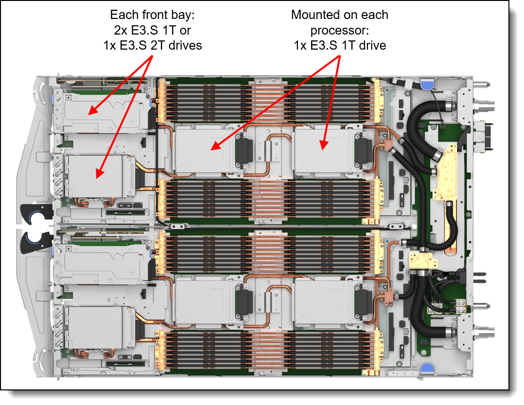
Figure 11. SC755 V5 internal drive bays
Configuration notes:
- The node supports only supports NVMe drives
- The drives are connected to onboard controllers; no RAID functionality is provided by the hardware, however you can use the OS RAID functionality if desired.
- NVMe drives are connected to CPUs as follows:
- Drives in front bay 1 connect to CPU 1
- Drives in front bay 2 connect to CPU 2
- Drives mounted on the CPUs are both connected to CPU 2
The feature codes to select the appropriate storage cage are listed in the following table. Quantities listed are per 2-socket node (in a 2N2S configuration)
Controllers for internal storage
The drives of the SC755 V5 are connected to integrated NVMe storage controllers.
RAID functionality is not provided by the server hardware. Use operating system-based RAID if desired.
Internal drive options
The following table list the drive options for internal storage of the server. Quantities listed are per 2-socket node.
I/O expansion
The SC755 V5 tray has 4x front accessible PCIe 6.0 x16 slots, configured as follows:
- 2-node 2-socket (2N2S) configuration - each node (A, C):
- Slot 1: Low Profile PCIe 6.0 x16 slot -- connected to CPU 1
- Slot 2: Low Profile PCIe 6.0 x16 slot or OCP (PCIe 6.0) x16 slot -- connected to CPU 2
- 4-node 1-socket (4N1S) configuration - each node (A, B, C, D):
- 1x Low Profile PCIe 6.0 x16 slot or OCP (PCIe 6.0) x16 slot
The server supports OCP adapters in the Low Profile PCIe slots with the addition of an additional OCP adapter cage.
The location of the slots is shown in the following figure.
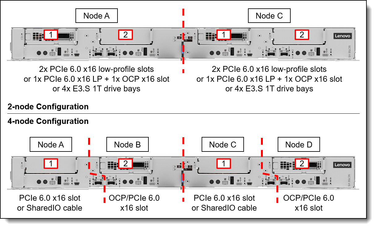
Figure 12. SC755 V5 PCIe slots
In this section:
Onboard ports
The SC755 V5 tray includes onboard 25Gb Ethernet network ports, connected to two onboard Broadcom 57504 controllers, one per 2-socket node. The ports are implemented with SFP28 cages for optical or copper connections. Ports support 10Gb and 25Gb connections (1Gb not supported).
Onboard port configuration is as follows:
- In a 2-node 2-socket (2N2S) configuration, each node has 2x onboard 25GbE ports. Port 1 in each node supports NC-SI for remote management.
- In a 4-node 1-socket (4N1S) configuration, each node has 1x onboard 25GbE port. The port in nodes A and C support NC-SI; the port in nodes B and D do not support NC-SI.
Locations of these ports is shown in the Components and connectors section. For CTO orders, you can specify if NC-SI is enabled or disabled by default in the factory. See the Remote Management section for details.
For the specifications of the 25GbE ports including the supported transceivers and cables, see the Broadcom 57504 product guide:
https://lenovopress.lenovo.com/lp1652-thinksystem-broadcom-57504-25gbe-ethernet-adapters
Riser ordering information
Slots are implemented using a 1-slot riser. Ordering information is in the following table.
PCIe slots can alternatively be configured as internal E3.S NVMe drive bays, as described in the Internal storage section.
Shared I/O
The SC755 V5 supports a feature called Shared I/O (SharedIO), also known as NVIDIA Networking Multi-Host technology, where a single network connection is shared between the two nodes in a tray. With Shared I/O, the NVIDIA adapter is installed in one node in a tray, and a suitable auxiliary cable is used to connect the adapter to a PCIe connector in the adjacent node in the same tray. The result is that the two nodes share the network connection of the adapter with significant savings both in the cost of the adapters but also the cost of switch ports.
See the table in the Network adapters section to see the adapters and cables that support Shared I/O.
Configuration rules:
- Shared I/O requires the use of an auxiliary cable or OCP cable
- For 2N2S:
- The PCIe adapter must be installed in slot 1 of node C. The cable connects the adapter to the onboard connector for slot 1 of node A.
- The OCP adapter must be installed in slot 2 of node C. The OCP cable connects the adapter to slot 2 of node B.
- For 4N1S:
- The PCIe adapter must be installed in slot 2 of node B and D. The cable connects the adapter to the onboard connector for slot 1 of node A and node C
- The OCP adapter must be installed in slot 2 of node B or node D. The OCP cable connects the adapter to node A and node C; or node A, B and C depending on the configuration.
Socket Direct
The SC755 V5 also supports a feature called Socket Direct where an adapter installed in a node is connected to both processors in that node at the same time. Socket Direct enables direct PCIe access to both processors, eliminating the need for network traffic having to traverse the inter-process bus. This optimizes overall system performance and maximum throughput for the most demanding applications and markets.
In the SC755 V5, Socket Direct is achieved by installing the NVIDIA adapter in slot 2 (connects to CPU 2) and an Aux cable or OCP cable is used to connect the adapter to the PCIe connector for slot 1 (which connects to CPU 1).
See the table in the Network adapters section to see the adapters and cables that support Socket Direct.
Configuration rules:
- Socket Direct requires the use of Aux or OCP cable.
- The adapter must be installed in Slot 2 of each node. The cable connects the adapter to the onboard connector for Slot 1.
- Slot 1 must remain empty if Socket Direct is configured; no drive or adapter can be installed.
- By default, ConnectX-7 adapters connect as PCIe Gen5 and the Auxiliary Cable connects as PCIe Gen4. This can be changed in UEFI.
- By default, ConnectX-8 adapters connect as PCIe Gen6 and the Auxiliary Cable connects as PCIe Gen5. This can be changed in UEFI.
Networking configurations
This section shows the different networking slot configurations, including Shared I/O and Socket Direct, for 2N2S and 4N1S, either with PCIe adapters or OCP adapters.
When implementing Shared I/O or Socket Direct, cables are used to connect network adapters to additional PCIe slots. An example of this is shown in the following figure, where a 4N1S configuration is enabled for Shared I/O. Each pair of nodes shares a single ConnectX-8 network adapter using an auxiliary cable.
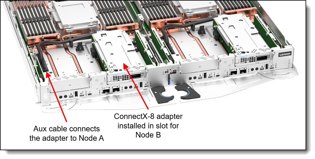
Figure 13. Shared I/O configuration with a 4-node 1-socket SC755 V5
In this section:
2N2S with PCIe adapters
The following figure shows the supported two-node 2-socket (2N2S) configurations using PCIe adapters.
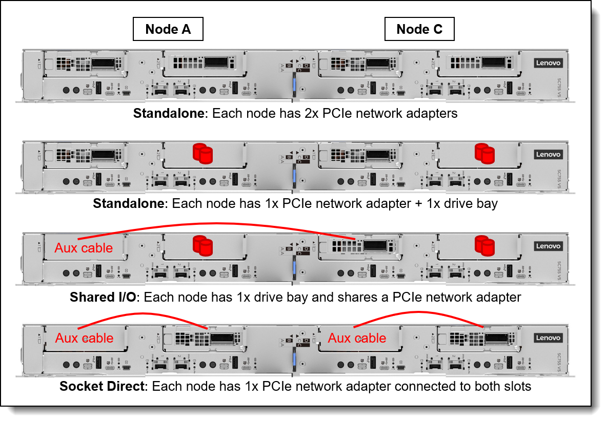
Figure 14. SC755 V5 slot configurations - 2N2S with PCIe adapters
The following table lists the cables required for each configuration. No networking cables are needed for the standalone configurations.
2N2S with OCP adapters
The following figure shows the supported two-node 2-socket (2N2S) configurations using OCP adapters.
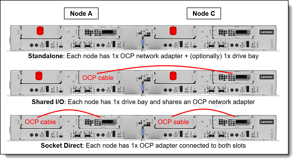
Figure 15. SC755 V5 slot configurations - 2N2S with OCP adapters
The following table lists the cables required for each configuration:
4N1S with PCIe adapters
The following figure shows the supported 4-node 1-socket (4N1S) configurations using PCIe adapters.
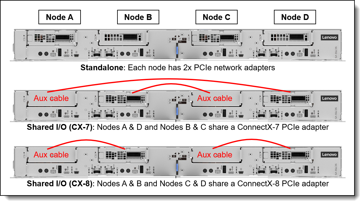
Figure 16. SC755 V5 slot configurations - 4N1S with PCIe adapters
The following table lists the cables required for each configuration. No networking cables are needed for the standalone configuration.
4N1S with OCP adapters
The following figure shows the supported 4-node 1-socket (4N1S) configurations using OCP adapters.
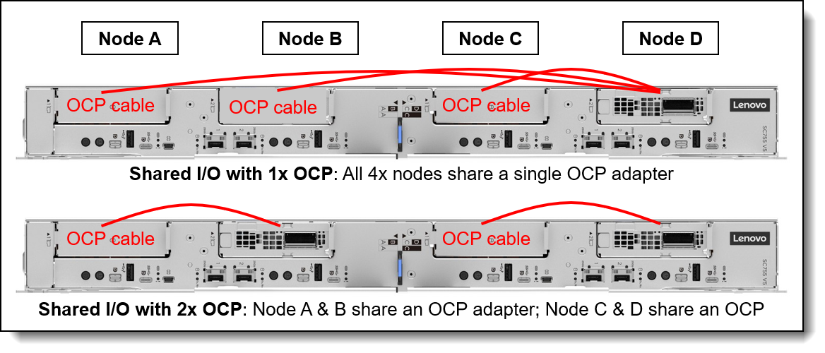
Figure 17. SC755 V5 slot configurations - 4N1S with OCP adapters
The following table lists the cables required for each configuration.
Network adapters
The SC755 V5 tray (2 nodes or 4 nodes, depending on the configuration) supports four network adapters installed in the PCIe slots. The following table lists the supported adapters. The node supports the SharedIO or Socket Direct features as indicated in the table. See the Shared I/O and Socket Direct sections for details.
† The ConnectX-9 9180 OCP adapter is planned to be orderable late 2026.
* Numbers in parentheses are the maximum supported per tray
** OCP adapter is only supported in Slot 2 (in a 4N configuration, this is Nodes B and D)
For more information, including the transceivers and cables that each adapter supports, see the list of Lenovo Press Product Guides in the Networking adapters category:
https://lenovopress.com/servers/options/ethernet
For SocketDirect and Shared I/O configurations, cables are needed depending on the adapter selected and the configuration of the tray. See the Networking configurations section for details on what cables are needed.
Cooling
One of the most notable features of the ThinkSystem SC755 V5 offering is direct water cooling. Direct water cooling (DWC) is achieved by circulating the cooling water directly through cold plates that contact the CPU thermal case, DIMMs, drives, adapters, and other high-heat-producing components in the node.
One of the main advantages of direct water cooling is the water can be relatively warm and still be effective because water conducts heat much more effectively than air. Depending on the environmentals like water and air temperature, effectively 100% of the heat can be removed by water cooling; in configurations that stay slightly below that, the rest can be easily managed by a standard computer room air conditioner.
Allowable inlet temperatures for the water can be as high as 45°C (113°F) with the SC755 V5 for real-world applications. In most climates, water-side economizers can supply water at temperatures below 45°C for most of the year. This ability allows the data center chilled water system to be bypassed thus saving energy because the chiller is the most significant energy consumer in the data center. Typical economizer systems, such as dry-coolers, use only a fraction of the energy that is required by chillers, which produce 6-10°C (43-50°F) water. The facility energy savings are the largest component of the total energy savings that are realized when the SC755 V5 is deployed.
The advantages of the use of water cooling over air cooling result from water’s higher specific heat capacity, density, and thermal conductivity. These features allow water to transmit heat over greater distances with much less volumetric flow and reduced temperature difference as compared to air.
For cooling IT equipment, this heat transfer capability is its primary advantage. Water has a tremendously increased ability to transport heat away from its source to a secondary cooling surface, which allows for large, more optimally designed radiators or heat exchangers rather than small, inefficient fins that are mounted on or near a heat source, such as a CPU.
The SC755 V5 offering uses the benefits of water by distributing it directly to the highest heat generating node subsystem components. By doing so, the offering realizes 7% - 10% direct energy savings when compared to an air-cooled equivalent. That energy savings results from the removal of the system fans and the lower operating temp of the direct water-cooled system components.
The direct energy savings at the enclosure level, combined with the potential for significant facility energy savings, makes the SC755 V5 an excellent choice for customers that are burdened by high energy costs or with a sustainability mandate.
Water is delivered to the enclosure from a coolant distribution unit (CDU) via water hoses, inlet and return. As shown in the following figure, each enclosure connects to the CDU via rack supply hoses.
The midplane in the enclosure routes the water via QuickConnects to each of the eight nodes, and each of the four power conversion stations.

Figure 18. N1380 enclosure water connections
The water flows through the SC755 V5 tray to cool all major heat-producing components. The inlet water is split into two parallel paths, one for each node in the tray. Each path is then split further to cool the processors, memory, drives, and adapters.
During the manufacturing and test cycle, Lenovo’s water-cooled nodes are pressure tested with Helium according to ASTM E499 / E499M – 11 (Standard Practice for Leaks Using the Mass Spectrometer Leak Detector in the Detector Probe Mode) and later again with Nitrogen to detect micro-leaks which may be undetectable by pressure testing with water and/or a water/glycol mixture as Helium and Nitrogen have smaller molecule sizes.
This approach also allows Lenovo to ship the systems pressurized without needing to send hazardous antifreeze-components to our customers.
Onsite the materials used within the water loop from the CDU to the nodes should be limited to copper alloys with brazed joints, Stainless steels with TIG and MIG welded joints and EPDM rubber. In some instances, PVC might be an acceptable choice within the facility.
The water the system is filled with must be reasonably clean, bacteria-free water (< 100 CFU/ml) such as de-mineralized water, reverse osmosis water, de-ionized water, or distilled water. It must be filtered with in-line 50 micron filter. Biocide and Corrosion inhibitors ensure a clean operation without microbiological growth or corrosion. For details about the implementation of Lenovo Neptune water cooling, see the document Lenovo Neptune Direct Water-Cooling Standards.
Lenovo Data Center Power and Cooling Services can support you in the design, implementation and maintenance of the facility water-cooling infrastructure.
Water connections
Water connections to the N1380 enclosure are provided using hoses that connect directly to the coolant distribution unit (CDU), either an in-rack CDU or in-row CDU. As shown in the following figure, hose lengths required depend on the placement of the N1380 in the rack cabinet.

Figure 19. Hose lengths based on the position of the N1380 enclosure in the rack cabinet
Water connections are made up of the following:
- Short hoses permanently attached to the rear of the N1380 enclosure
- Intermediate hoses, orderable as three different pairs of hoses, based on the location of the N1380 enclosure in the rack. Ordering information for these hoses is listed in the table below.
- Connection to the CDU through additional hoses or valves on the data center water loop. Lenovo Datacenter Services can provide the end-to-end enablement for your water infrastructure needs.
The Intermediate hoses have a Sanitary Flange with a 1.5-inch Tri-Clamp at the CDU/data center end, as shown in the figure below.

Figure 20. Connections of the Intermediate hoses
Ordering information for the Intermediate hoses to supply and return the water are listed in the following table. Hoses can either be stainless steel or EPDM, depending on the data center requirements.
For additional information, see the Cooling section.
To support the onsite setup for the direct water-cooled solution, a Commissioning Kit is available providing a flow meter, bleed hose, pressure gauge and vent valve. Ordering information is listed in the following table. Either kit supports the N1380 enclosure.
Power conversion stations
The N1380 enclosure supports up to four water-cooled Power Conversion Stations. The use of water-cooled power conversion stations enables an even greater amount of heat can be removed from the data center using water instead of air-conditioning.
The Power Conversion Stations supply internal system power to a 48V busbar. This innovative design merges power conversion, rectification, and distribution into a single unit, a departure from traditional setups that require separate units, including separate power supplies, resulting in best-in-class efficiency.

Figure 21. N1380 power conversion stations
The N1380 supports the power conversion stations listed in the following table.
Quantities of 2, 3 or 4 are supported. The power conversion stations provide N+1 redundancy with oversubscription.
Tip: Use Lenovo Capacity Planner to determine the power needs for your rack installation. See the Lenovo Capacity Planner section for details.
The power conversion stations have the following features:
- 80 PLUS Titanium certified
- Input: 380~480Vac, 3-phase WYE
- Input current: 30A per phase)
- N+1 power redundancy
- Power management configured through the SMM
- Built-in overload and surge protection
- Full telemetry of PCS available through SMM GUI or Redfish including: energy, power, voltage, current, and overall conversion efficiency
Power policies and power output
The following table lists the enclosure power capacity based on the power policy and the number of power modules installed.
* The numbers in parentheses are the chassis power capacity if no throttling is required when the redundancy is degraded (e.g. 3+1 and 1 PSU fails)
Notes in the table:
- N+1+OVS (oversubscription) is the default if >1 PSU is installed. N+0 is the default with 1 PSU installed.
- If N+N is selected and there is an AC domain fault (2 PSUs go down), the power capacity is reduced to the value shown in parentheses within 1 second. Example: If 2+2 policy is selected & all 4 PSUs are operational, the power capacity is 36KWDC. If an AC domain faults, 2 PSU go down, and the power is reduced to 30KW within 1 second
- If N+1 is selected and there is a PSU fault, the power capacity is reduced to <= the value shown in parentheses within 1 second. Example: If 3+1 policy is selected & all 4 PSUs are operational, the power capacity is 54KWDC. If a PSU faults, the power is reduced to <=45KW within 1 second. GPU trays are hard throttled w PWRBRK#. Intel trays are proprotionally throttled with Psys power capping
- If the chassis is in the degraded redundancy state, due to 1 or more PSU faults, and an additional PSU fails, the chassis will attempt to stay alive by hard-throttling the trays (via PROCHOT# & PWRBRK#), but there is no guarantee. There is risk that the chassis could power off if the PSU rating is exceeded
- For the redundant power policies, only OVS modes are selectable in SMM (ie. OVS is always enabled). When a user creates a hardware config in DCSC, a chassis max power estimate is completed, via an LCP API call. If the chassis DC max power is in between the chassis degraded power capacity shown in parentheses and the chassis normal power capacity, a warning is displayed stating that the server could be throttled if a PSU fails. If the customer doesn’t want potential throttling, they either need to reduce their config or select a different combo of PSUs/policy to achieve a higher power budget
- Possible future feature
Power cables
The power conversion stations function at a 32A current, but the power cables enable two PCS units to share a single 63A connection from the data center. Consequently, for racks fully equipped with 12 power conversion stations, only six power connections from the data center are needed.
The N1380 enclosure supports the following power cables.
System Management
The SC755 V5 servers contain an integrated service processor, XClarity Controller 4 (XCC4), which provides advanced control, monitoring, and alerting functions. The XCC4 is based on the AST2700 baseboard management controller (BMC) using a dual-core ARM Cortex A7 32-bit RISC service processor running at 1.2 GHz.
Each SC755 V5 node has its own XCC4 service processor, implemented on a DC-SCM module.
- When the tray is configured as two nodes, 2x DC-SCM module (2x XCC4 service processors) are installed
- When the tray is configured as four nodes, 4x DC-SCM module (4x XCC4 service processors) are installed
The DC-SCMs are located at the front of the servers as shown in the figure below.
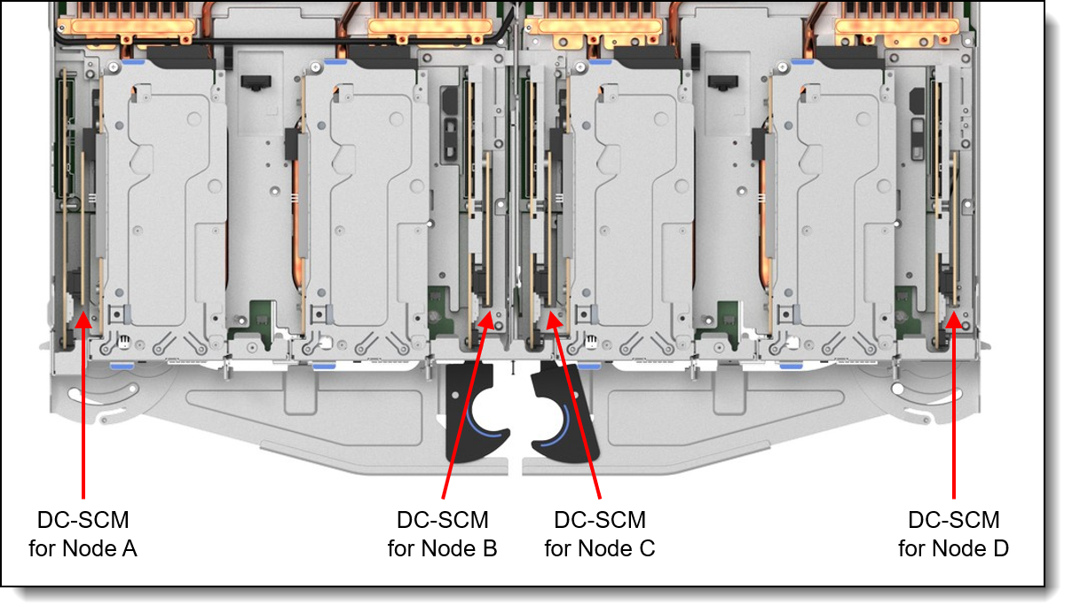
Figure 22. Locations of the DC-SCMs
Topics in this section:
- DC-SCM module
- Local management
- Remote management
- XCC Premier
- Remote management using the SMM3
- Lenovo HPC & AI Software Stack
- Lenovo XClarity Provisioning Manager
- Lenovo XClarity Essentials
- Lenovo XClarity One
- Lenovo XClarity Energy Manager
- Lenovo Capacity Planner
Tip: XClarity Mobile is not supported in the SC755 V5.
DC-SCM module
The SC755 V5 implements the DC-SCM (Data Center Secure Control Module or DCSCM) as 2 or 4 modules installed in the tray in dedicated locations. One DC-SCM module is installed for each node - two in a 2N2S configuration and four in a 4N1S configuration.
The DC-SCM in the SC755 V5 is a 1U CFF (compact form factor) module, as shown in the following figure.
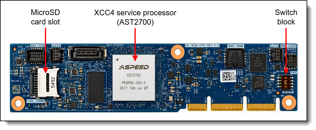
The module also has the following components:
- XClarity Controller 4, implemented using the ASPEED AST2700 baseboard management controller (BMC).
- Root of Trust (RoT) module - implements Platform Firmware Resiliency (PFR) hardware Root of Trust (RoT) which enables the server to be NIST SP800-193 compliant. For more details about PFR, see the Security section.
- MicroSD card port to enable the use of a MicroSD card for additional storage for use with the XCC4 controller. XCC4 can use the storage as a Remote Disc on Card (RDOC) device (up to 4GB of storage). It can also be used to store firmware updates (including N-1 firmware history) for ease of deployment.
Tip: Without a MicroSD card installed, the XCC controller will have 100MB of available RDOC storage.
Note: Customers will need to supply their own MicroSD card for use in this card slot. Lenovo does not offer a MicroSD card for use in the SC755 V5.
DC-SCM field upgrades
For field upgrades to convert a 2-node (2N2S) configuration to a 4-node configuration (4N1S), you will need to add the additional DC-SCMs. A 2-node configuration has 2x DC-SCMs and a 4-node configuration has 4x DC-SCMs, so an upgrade will require 2 additional DC-SCMs, as listed in the following table.
Local management
The front of the SC755 V5 tray contains the controls for all nodes (2 or 4 nodes, depending on the node configuration). The following figure shows the placement of each node's controls.
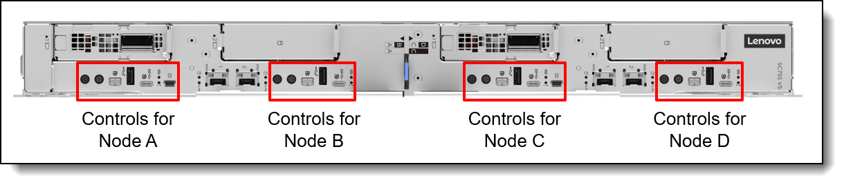
Figure 24. Front controls for all nodes
Ports in a 2-node config: In a 2-node 2-socket (2N2S) config, the ports and controls for Nodes B and D are disabled except for the USB-A ports for those node.All four USB-A ports are still enabled.
The following figure shows the ports and LEDs for Node A.
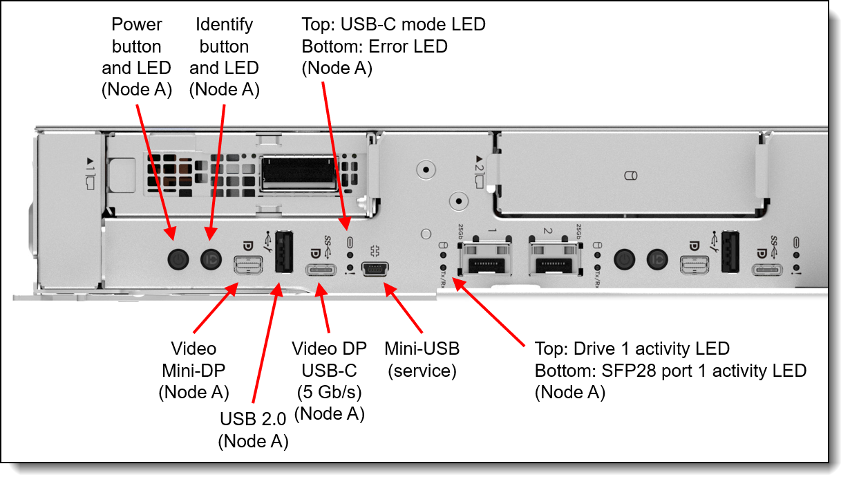
Figure 25. SC755 V5 Front operator panel
The LEDs are as follows:
- Identification (ID) LED (blue): Activated remotely via XCC to identify a specific server to local service engineers
- Error LED (yellow): Indicates if there is a system error. The error is reported in the XCC system log.
- USB-C mode LED: To be confirmed
Information pull-out tab
The front of the tray also houses an information pull-out tab (also known as the network access tag). See Figure 2 for the location. A label on the tab shows the network information (MAC address and other data) to remotely access the service processor.
Mini-USB debug port
The SC755 V5 tray implements two mini-USB ports (one per 2-socket node) located at the front of the tray. This debug port is for BMC serial console output and is for servicer user only. The use of the port requires proper authentication by the XCC4 service processor.
Remote management
Port 1 of each pair of 25Gb onboard ports on the front of the SC755 V5 offers a connection to the XCC for remote management. This shared-NIC functionality allows the ports to be used both for operating system networking and for remote management.
Remote server management is provided through industry-standard interfaces:
- Intelligent Platform Management Interface (IPMI) Version 2.0
- Simple Network Management Protocol (SNMP) Version 3 (no SET commands; no SNMP v1)
- Common Information Model (CIM-XML)
- Representational State Transfer (REST) support
- Redfish support (DMTF compliant)
- Web browser - HTML 5-based browser interface (Java and ActiveX not required) using a responsive design (content optimized for device being used - laptop, tablet, phone) with NLS support
Port 1 of each pair of 25Gb onboard ports supports NC-SI. You can enable NC-SI in the factory using the feature codes listed in the following table. If neither feature code is selected, the ports will have NC-SI disabled as shipped from the factory.
IPMI via the Ethernet port (IPMI over LAN) is supported, however it is disabled by default. For CTO orders you can specify whether you want to the feature enabled or disabled in the factory, using the feature codes listed in the following table.
XCC Premier
The XCC service processor in the SC755 V5 supports an upgrade to the Premier level of features. XCC Premier in ThinkSystem V5 and V4 servers is equivalent to the XCC2 Premium offering in ThinkSystem V3 servers.
XCC Premier adds the following functions:
- System Guard - Monitor hardware inventory for unexpected component changes, and simply log the event or prevent booting
- Neighbor Group - Enables administrators to manage and synchronize configurations and firmware level across multiple servers
- Syslog alerting
- Lenovo SED security key management
- Boot video capture and crash video capture
- Virtual console collaboration - Ability for up to 6 remote users to be log into the remote session simultaneously
- Remote console
- System utilization data and graphic view
- Update firmware from a repository
- Enterprise Strict Security mode - Enforces CNSA 1.0 level security
- Remotely viewing video with graphics resolutions up to 1600x1200 at 75 Hz with up to 23 bits per pixel, regardless of the system state
- Remotely accessing the server using the keyboard and mouse from a remote client
- International keyboard mapping support
- Redirecting serial console via SSH
- Component replacement log (Maintenance History log)
- Access restriction (IP address blocking)
- Displaying graphics for real-time and historical power usage data and temperature
- Mapping the ISO and image files located on the local client as virtual drives for use by the server
- Mounting the remote ISO and image files via HTTPS, SFTP, CIFS, and NFS
- License for XClarity Energy Manager
Note: The SC755 V5 does not support Power capping.
Ordering information is listed in the following table. XCC Premier is a software license upgrade - no additional hardware is required.
| Part number | Feature code | Description |
|---|---|---|
| 7S0X000XWW | SCY0 | Lenovo XClarity Premier |
With XCC Premier, for CTO orders, you can request that System Guard be enabled in the factory and the first configuration snapshot be recorded. To add this to an order, select feature code listed in the following table. The selection is made in the Security tab of the configurator.
| Feature code | Description |
|---|---|
| BUT2 | Enable System Guard |
For more information about System Guard, see https://pubs.lenovo.com/xcc3/nn1ia_c_systemguard
Remote management using the SMM3
The N1380 enclosure includes a System Management Module 3 (SMM), installed in the rear of the enclosure. See Enclosure rear view for the location of the SMM. The SMM provides remote management of both the enclosure and the individual servers installed in the enclosure. The SMM can be accessed through a web browser interface and via Intelligent Platform Management Interface (IPMI) 2.0 commands.
The SMM provides the following functions:
- Remote connectivity to XCC controllers in each node in the enclosure
- Node-level reporting and control (for example, node virtual reseat/reset)
- Enclosure power management
- Enclosure thermal management
- Enclosure inventory
The following figure shows the LEDs and connectors of the SMM.

The SMM has the following ports and LEDs:
- 2x Gigabit Ethernet RJ45 ports for remote management access
- USB port and activation button for service
- SMM reset button
- System error LED (yellow)
- Identification (ID) LED (blue)
- Status LED (green)
- System power LED (green)
The USB service button and USB service port are used to gather service data in the event of an error. Pressing the service button copies First Failure Data Collection (FFDC) data to a USB key installed in the USB service port. The reset button is used to perform an SMM reset (short press) or to restore the SMM back to factory defaults (press for 4+ seconds).
The use of two RJ45 Ethernet ports enables the ability to daisy-chain the Ethernet management connections thereby reducing the number of ports you need in your management switches and reducing the overall cable density needed for systems management. With this feature you can connect the first SMM to your management network and the SMM in a second enclosure connects to the first SMM. The SMM in the third enclosure can then connect to the SMM in the second enclosure.
Up to 3 enclosures can be connected in a daisy-chain configuration and all 48 servers in those enclosures can be managed remotely via one single Ethernet connection.
Notes:
- If you are using IEEE 802.1D spanning tree protocol (STP) then at most 3 enclosures can be connected together
- Do not form a loop with the network cabling. The dual-port SMM at the end of the chain should not be connected back to the switch that is connected to the top of the SMM chain.
Lenovo HPC & AI Software Stack
The Lenovo HPC & AI Software Stack combines open-source with proprietary best-of-breed Supercomputing software to provide the most consumable open-source HPC software stack embraced by all Lenovo HPC customers.
It provides a fully tested and supported, complete but customizable HPC software stack to enable the administrators and users in optimally and environmentally sustainable utilizing their Lenovo Supercomputers.
The Lenovo HPC & AI Software Stack is built on the most widely adopted and maintained HPC community software for orchestration and management. It integrates third party components especially around programming environments and performance optimization to complement and enhance the capabilities, creating the organic umbrella in software and service to add value for our customers.
The key open-source components of the software stack are as follows:
- Confluent Management
Confluent is Lenovo-developed open-source software designed to discover, provision, and manage HPC clusters and the nodes that comprise them. Confluent provides powerful tooling to deploy and update software and firmware to multiple nodes simultaneously, with simple and readable modern software syntax.
- Slurm Orchestration
Slurm is integrated as an open source, flexible, and modern choice to manage complex workloads for faster processing and optimal utilization of the large-scale and specialized high-performance and AI resource capabilities needed per workload provided by Lenovo systems. Lenovo provides support in partnership with NVIDIA.
-
Slinky
Slinky Bridge is a software solution that enables HPC and AI convergence by allowing Slurm and Kubernetes workloads to share the same compute infrastructure. Acting as the source of truth for scheduling decisions, Slurm extends its scheduling, accounting, and resource management capabilities to Kubernetes workloads while maintaining support for traditional HPC jobs. This unified approach reduces GPU fragmentation, improves resource utilization, and allows organizations to support both HPC and cloud-native AI workflows on a common platform. - Energy Aware Runtime
EAR is a powerful European open-source energy management suite supporting anything from monitoring over power capping to live-optimization during the application runtime. Lenovo collaborates with Barcelona Supercomputing Centre (BSC) and Energy Aware Solutions (EAS) on the continuous development and support and offers three versions with differentiating capabilities.
-
Open OnDemand
Open OnDemand (OOD) is an open source, web-based access portal that provides a unified Graphical User Interface (GUI) for seamless access to HPC and AI clusters. It enables users to securely access compute resources, submit and monitor jobs, and launch rich interactive applications, such as Jupyter Notebooks, VS Code, RStudio, and TensorBoard, directly from a standard web browser. Through these interactive environments, OOD enables end-users to run complete AI and data-science workflows based on popular frameworks like TensorFlow, PyTorch, RAPIDS, and more, without needing to manage the underlying cluster complexity. Supporting multiple resource managers, including Slurm, PBS Pro, LSF, and Kubernetes, Open OnDemand makes it easy to consolidate HPC and AI workloads on a shared infrastructure, significantly improving usability, accessibility, and overall productivity while eliminating the need for command-line expertise.
For more information and ordering information, see the Lenovo HPC & AI Software Stack product guide:
https://lenovopress.lenovo.com/lp1651-lenovo-hpc-ai-software-stack
Lenovo XClarity Provisioning Manager
Lenovo XClarity Provisioning Manager (LXPM) is a UEFI-based application embedded in ThinkSystem servers and accessible via the F1 key during system boot.
LXPM provides the following functions:
- Graphical UEFI Setup
- System inventory information and VPD update
- System firmware updates (UEFI and XCC)
- RAID setup wizard
- OS installation wizard (including unattended OS installation)
- Diagnostics functions
Lenovo XClarity Essentials
Lenovo offers the following XClarity Essentials software tools that can help you set up, use, and maintain the server at no additional cost:
- Lenovo Essentials OneCLI
OneCLI is a collection of server management tools that uses a command line interface program to manage firmware, hardware, and operating systems. It provides functions to collect full system health information (including health status), configure system settings, and update system firmware and drivers.
- Lenovo Essentials UpdateXpress
The UpdateXpress tool is a standalone GUI application for firmware and device driver updates that enables you to maintain your server firmware and device drivers up-to-date and help you avoid unnecessary server outages. The tool acquires and deploys individual updates and UpdateXpress System Packs (UXSPs) which are integration-tested bundles.
- Lenovo Essentials Bootable Media Creator
The Bootable Media Creator (BOMC) tool is used to create bootable media for offline firmware update.
For more information and downloads, visit the Lenovo XClarity Essentials web page:
http://support.lenovo.com/us/en/documents/LNVO-center
Lenovo XClarity One is a cloud-native unified Management-as-a-Service (MaaS) platform, engineered to modernize IT infrastructure. .
XClarity One is the next milestone in Lenovo’s portfolio of systems management products. Now you can leverage the benefits of a true next-generation platform for the deployment, management, and maintenance of your infrastructure through a single, centralized platform that delivers a consistent user experience across all Lenovo products.
XClarity One's primary architectural value is divided into three key areas:
- How it predicts issues (AI/Analytics)
- How it securely connects (Secure Management Hubs),
- How it actually configures the hardware at scale (Template-Driven Lifecycle Control)
AI-powered Automation
XClarity One harnesses the power of AI and predictive analytics to enhance the performance and reliability of your infrastructure with proactive protection.
- AI-Powered Predictive Failure Analytics - XC1 utilizes machine learning infrastructure to look at live device telemetries. The platform securely collects memory-diagnostic logs and pushes them into an active MPFA AI model infrastructure to analyze health patterns and predict probable hardware degradation before it manifests as a hard failure.
- AI-Powered Call-Home - A Call-Home serviceable event opens a support ticket automatically, leveraging AI technology (in the case of MPFA) for problem determination and fast resolution automatically dispatching parts and services, reducing service costs and minimizing downtime.
Secure Management Hub
Lenovo’s proprietary Management Hub is an on-premises virtual appliance that acts as the bridge between your infrastructure and the cloud.
- On-Premises Security with Cloud Flexibility - your infrastructure has no direct connection to the cloud, greatly reducing your attack surface from external threats while still having the deployment benefits, flexibility, and scalability of a cloud solution.
- Authentication and Authorization - built on a Zero Trust Architecture and requiring OTP Application authentication for all users to handle the support of all customers’ servers and client devices. Role-based access controls help define and restrict permissions based on user roles.
Template-Driven Lifecycle Control
Lenovo’s unified management model eliminates fragmented server administration, allowing you to deploy, track, and maintain your entire infrastructure fleet from a single cloud-native dashboard.
- Automated Configuration and Compliance: Leverage scalable, repeatable device templates to rapidly deploy firmware updates, operating systems, and core baseboard management controller (BMC/UEFI) simultaneously across multiple sites. XClarity One continuously analyzes hardware compliance, shifting out-of-compliance systems to a critical status until a template re-deployment aligns them back to corporate standards.
- Global Asset Visibility and Fleet Telemetry: Centralize real-time tracking of component health, warranty status, and comprehensive hardware inventories. The platform aggregates live usage data, including memory allocation, power consumption, and processor thermal trends, giving you total operational awareness whether a server resides in a centralized data center or a remote edge environment.
Centralized management via Lenovo XClarity One can be integrated into your environment as an optional component. License information for XClarity One is listed in the following table.
Licensing notes:
- One license is needed per physical managed device.
- Starter license is functionally identical to Standard license but is limited to 10 devices per organization maximum.
For more information, see these resources:
- Lenovo XClarity One datasheet:
https://lenovopress.lenovo.com/ds0188-lenovo-xclarity-one - Lenovo XClarity One product guide:
https://lenovopress.lenovo.com/lp1992-lenovo-xclarity-one - Migrating to Lenovo XClarity One: An Overview:
https://lenovopress.lenovo.com/lp2429-migrating-to-lenovo-xclarity-one-an-overview
Lenovo XClarity Energy Manager
Lenovo XClarity Energy Manager (LXEM) is a power and temperature management solution for data centers. It is an agent-free, web-based console that enables you to monitor and manage power consumption and temperature in your data center through the management console. It enables server density and data center capacity to be increased through the use of power capping.
LXEM is a licensed product. A single-node LXEM license is included with the XClarity Controller Enterprise upgrade as described in the Remote Management section. If your server does not have the XCC Enterprise upgrade, Energy Manager licenses can be ordered as shown in the following table.
| Part number | Description |
|---|---|
| 4L40E51621 | Lenovo XClarity Energy Manager Node License (1 license needed per server) |
For more information about XClarity Energy Manager, see the following resources:
- Lenovo Support page:
https://datacentersupport.lenovo.com/us/en/solutions/lnvo-lxem - User Guide for XClarity Energy Manager:
https://pubs.lenovo.com/lxem/
Lenovo Capacity Planner
Lenovo Capacity Planner is a power consumption evaluation tool that enhances data center planning by enabling IT administrators and pre-sales professionals to understand various power characteristics of racks, servers, and other devices. Capacity Planner can dynamically calculate the power consumption, current, British Thermal Unit (BTU), and volt-ampere (VA) rating at the rack level, improving the planning efficiency for large scale deployments.
For more information, refer to the Capacity Planner web page:
http://datacentersupport.lenovo.com/us/en/solutions/lnvo-lcp
Security
Topics in this section:
Security features
The server offers the following electronic security features:
- Secure Boot function of the AMD processor
- Support for Platform Firmware Resiliency (PFR) hardware Root of Trust (RoT) - see the Platform Firmware Resiliency section
- Firmware signature processes compliant with FIPS and NIST requirements
- System Guard (part of XCC Premier) - Proactive monitoring of hardware inventory for unexpected component changes
- Administrator and power-on password
- Integrated Trusted Platform Modules (TPM) supporting TPM 2.0, one per node (2 or 4 per SC755 V5 tray)
- For China users, optional Nationz TPM 2.0 modules
- Self-encrypting drives (SEDs) with support for enterprise key managers
The server is NIST SP 800-147B compliant.
The following table lists the security options for the SC755 V5. One TPM is needed for each node (2 or 4 per SC755 V5 tray).
| Part number | Feature code | Description | Quantity |
|---|---|---|---|
| CTO only | C1YL | ThinkSystem V4 PRC NationZ TPM 2.0 Module (China customers only) | 2 or 4 (1 per node) |
Platform Firmware Resiliency - Lenovo ThinkShield
Lenovo's ThinkShield Security is a transparent and comprehensive approach to security that extends to all dimensions of our data center products: from development, to supply chain, and through the entire product lifecycle.
The ThinkSystem SC755 V5 includes Platform Firmware Resiliency (PFR) hardware Root of Trust (RoT) which enables the system to be NIST SP800-193 compliant. This offering further enhances key platform subsystem protections against unauthorized firmware updates and corruption, to restore firmware to an integral state, and to closely monitor firmware for possible compromise from cyber-attacks.
PFR operates upon the following server components:
- UEFI image – the low-level server firmware that connects the operating system to the server hardware
- XCC image – the management “engine” software that controls and reports on the server status separate from the server operating system
- FPGA image – the code that runs the server’s lowest level hardware controller on the motherboard
The Lenovo Platform Root of Trust Hardware performs the following three main functions:
- Detection – Measures the firmware and updates for authenticity
- Recovery – Recovers a corrupted image to a known-safe image
- Protection – Monitors the system to ensure the known-good firmware is not maliciously written
These enhanced protection capabilities are implemented using a dedicated, discrete security processor whose implementation has been rigorously validated by leading third-party security firms. Security evaluation results and design details are available for customer review – providing unprecedented transparency and assurance.
The SC755 V5 includes support for Secure Boot, a UEFI firmware security feature developed by the UEFI Consortium that ensures only immutable and signed software are loaded during the boot time. The use of Secure Boot helps prevent malicious code from being loaded and helps prevent attacks, such as the installation of rootkits. Lenovo offers the capability to enable secure boot in the factory, to ensure end-to-end protection. Alternatively, Secure Boot can be left disabled in the factory, allowing the customer to enable it themselves at a later point, if desired.
The following table lists the relevant feature code(s).
Tip: If Secure Boot is not enabled in the factory, it can be enabled later by the customer. However once Secure Boot is enabled, it cannot be disabled.
Security standards
The SC755 V5 supports the following security standards and capabilities:
- Industry Standard Security Capabilities
- AMD CPU Enablement
- AES-NI (Advanced Encryption Standard New Instructions)
- GMET (Guest Mode Execute Trap)
- Hardware-based side channel attack resilience enhancements
- NX (No eXecute)
- PSB (Platform Secure Boot)
- Shadow Stack
- SEV (Secure Encrypted Virtualization)
- SEV-ES (Encrypted State register encryption)
- SEV-SNP (Secure Nested Paging)
- TEE Device Interface Security protocol (TDISP)
- TSME (Transparent Secure Memory Encryption)
- SVM (Secure Virtual Machine)
- UMIP (User Mode Instruction Prevention)
- Microsoft Windows Security Enablement
- Credential Guard
- Device Guard
- Host Guardian Service
- TPM 2.0 (Trusted Platform Module 2.0)
- UEFI (Unified Extensible Firmware Interface) Forum Secure Boot
- AMD CPU Enablement
- Hardware Root of Trust and Security
- Independent security subsystem providing platform-wide NIST SP800-193 compliant Platform Firmware Resilience (PFR) that is CNSA 2.0 Compliant
- Host domain RoT supplemented by AMD Platform Secure Boot (PSB)
- Management domain RoT provided by the Secure Boot feature of the Baseboard Management Controller (BMC)
- Platform Security
- Boot and run-time firmware integrity monitoring with rollback to known-good firmware (e.g., “self-healing”)
- Non-volatile storage bus security monitoring and filtering
- Resilient firmware implementation, such as to detect and defeat unauthorized flash writes or SMM (System Management Mode) memory incursions
- Patented IPMI KCS channel privileged access authorization (USPTO Patent# 11,256,810)
- Host and management domain authorization, including integration with CyberArk for enterprise password management
- KMIP (Key Management Interoperability Protocol) compliant, including support for IBM SKLM and Thales KeySecure
- Reduced “out of box” attack surface
- Configurable network services
- FIPS 140-3 validated cryptography for XCC (Certificate # 5548)
- CNSA Suite 1.0 Quantum-resistant cryptography for XCC (included with XCC4 Premier)
- CNSA 2.0 compliant firmware update signatures verified by XCC
- CNSA 2.0 and post-quantum protocol support enabled where available.
- Lenovo System Guard
For more information on platform security, see the paper “How to Harden the Security of your ThinkSystem Server and Management Applications” available from https://lenovopress.com/lp1260-how-to-harden-the-security-of-your-thinksystem-server.
- Standards Compliance and/or Support
- NIST SP800-131A rev 2 “Transitioning the Use of Cryptographic Algorithms and Key Lengths”
- NIST SP800-147B “BIOS Protection Guidelines for Servers”
- NIST SP800-193 “Platform Firmware Resiliency Guidelines”
- ISO/IEC 11889 “Trusted Platform Module Library”
- Common Criteria TCG Protection Profile for “PC Client Specific TPM 2.0”
- European Union Commission Regulation 2019/424 (“ErP Lot 9”) “Ecodesign Requirements for Servers and Data Storage Products” Secure Data Deletion
- FIPS 140-3 validated cryptography for XCC (Certificate # 5548)
- CNSA Suite 1.0 Quantum-resistant cryptography for XCC (included with XCC4 Premier)
- Optional FIPS 140-2 validated Self-Encrypting Disks (SEDs) with external KMIP-based key management
- Product and Supply Chain Security
- Suppliers validated through Lenovo’s Trusted Supplier Program
- Developed in accordance with Lenovo’s Secure Development Lifecycle (LSDL)
- Continuous firmware security validation through automated testing, including static code analysis, dynamic network and web vulnerability testing, software composition analysis, and subsystem-specific testing, such as UEFI security configuration validation
- Ongoing security reviews by US-based security experts, with attestation letters available from our third-party security partners
- Digitally signed firmware, stored and built on US-based infrastructure and signed on US-based Hardware Security Modules (HSMs)
- TAA (Trade Agreements Act) compliant manufacturing, by default in Mexico for North American markets with additional US and EU manufacturing options
- US 2019 NDAA (National Defense Authorization Act) Section 889 compliant
Operating system support
The SC755 V5 supports the following operating systems:
- Red Hat Enterprise Linux 9.8
- Red Hat Enterprise Linux 10.2
- SUSE Linux Enterprise Server 16.1
- Ubuntu 24.04.5 LTS 64-bit
- Ubuntu 26.04 LTS 64-bit
The server is also certified or tested with the following operating systems:
- Rocky Linux
- Alma Linux
See Operating System Interoperability Guide (OSIG) for the complete list of supported, certified, and tested operating systems, including version and point releases:
https://lenovopress.lenovo.com/osig
Also review the latest LeSI Best Recipe to see the operating systems that are supported via Lenovo Scalable Infrastructure (LeSI):
https://support.lenovo.com/us/en/solutions/HT505184#5
Physical and electrical specifications
Eight SC755 V5 server trays are installed in the N1380 enclosure. Each SC755 V5 tray has the following dimensions:
- Width: 546 mm (21.5 inches)
- Height: 53 mm (2.1 inches)
- Depth: 760 mm (29.9 inches) (799 mm, including the water connections at the rear of the server)
The N1380 enclosure has the following overall physical dimensions, excluding components that extend outside the standard chassis, such as EIA flanges, front security bezel (if any), and power conversion station handles:
- Width: 540 mm (21.3 inches)
- Height: 572 mm (22.5 inches)
- Depth: 1302 mm (51.2 inches)
The following table lists the detailed dimensions. See the figure below for the definition of each dimension.

The shipping (cardboard packaging) dimensions of the SC755 V5 are as follows:
- Width: 800 mm (31.5 inches)
- Height: 260 mm (10.2 inches)
- Depth: 1200 mm (47.2 inches)
The shipping (cardboard packaging) dimensions of the N1380 are as follows:
- Width: 800 mm (31.5 inches)
- Height: 1027 mm (40.4 inches)
- Depth: 1600 mm (63.0 inches)
The SC755 V5 tray has the following maximum weight:
- 36.5 kg (80.5 lb)
The N1380 enclosure has the following weight:
- Empty enclosure (with midplane and cables): 94 kg (208 lbs)
- Fully configured enclosure with 4x water-cooled power conversion stations and 8x SC755 V5 server trays (16 nodes): 470 kg (1036 lb)
The enclosure has the following electrical specifications for input power conversion stations:
- Input voltage: 180-528Vac (nominal 200-480Vac), 3-phase, WYE
- Input current (each power conversion station): 30A
Operating environment
The SC755 V5 server trays and N1380 enclosure are supported in the following environment.
Topics in this section:
Air temperature and humidity
Air temperature/humidity requirements:
- Operating - ASHRAE A3: 5°C to 40°C (41°F to 104°F); the maximum ambient temperature decreases by 1°C for every 175 m (574 ft) increase in altitude above 900 m (2,953 ft).
- Powered off: 5°C to 45°C (41°F to 113°F)
- Shipping/storage: -40°C to 60°C (-40°F to 140°F)
- Operating humidity - ASHRAE Class A3: 8% to 85%; maximum dew point: 24°C (75°F)
- Shipment/storage humidity: 8% - 90%
Altitude:
- Maximum altitude: 3048 m (10 000 ft)
Particulate contamination
Airborne particulates (including metal flakes or particles) and reactive gases acting alone or in combination with other environmental factors such as humidity or temperature might damage the system that might cause the system to malfunction or stop working altogether.
The following specifications indicate the limits of particulates that the system can tolerate:
- Reactive gases:
- The copper reactivity level shall be less than 200 Angstroms per month (Å/month)
- The silver reactivity level shall be less than 200 Å/month
- Airborne particulates:
- The room air should be continuously filtered with MERV 8 filters.
- Air entering a data center should be filtered with MERV 11 or preferably MERV 13 filters.
- The deliquescent relative humidity of the particulate contamination should be more than 60% RH
- Environment must be free of zinc whiskers
For additional information, see the Specifications section of the documentation for the server, available from the Lenovo Documents site, https://pubs.lenovo.com/
Regulatory compliance
The SC755 V5 conforms to the following standards:
- ANSI/UL 62368-1
- CE, UKCA Mark (EN55032 Class A, EN62368-1, EN55035, EN61000-3-11, EN61000-3-12, (EU) 2019/424, and EN IEC 63000 (RoHS))
- FCC - Verified to comply with Part 15 of the FCC Rules, Class A
- Canada ICES-003, issue 7, Class A
- CISPR 32, Class A, CISPR 35
- Korea KS C 9832 Class A, KS C 9835
- Japan VCCI, Class A
- Taiwan BSMI CNS15936, Class A; Section 5 of CNS15663
- Australia/New Zealand AS/NZS CISPR 32, Class A; AS/NZS 62368.1
- Japanese Energy-Saving Act
- EU2019/424 Energy Related Product (ErP Lot9)
- China CELP certificate, HJ 2507-2011
- China RoHS certificate, GB26572
The N1380 conforms to the following standards:
- ANSI/UL 62368-1
- IEC 62368-1 (CB Certificate and CB Test Report)
- CSA C22.2 No. 62368-1
- Argentina IEC 62368-1
- Mexico NOM-019
- Ukraine UkrCEPRO
- Morocco CMIM Certification (CM)
- Russia, Belorussia and Kazakhstan, TP EAC 037/2016 (for RoHS)
- Russia, Belorussia and Kazakhstan, EAC: TP TC 004/2011 (for Safety); TP TC 020/2011 (for EMC)
- CE, UKCA Mark (EN55032 Class A, EN62368-1, EN55035,(EN61000-3-2, EN61000-3-3 or EN61000-3-11, EN61000-3-12) , (EU) 2019/424, and EN IEC 63000 (RoHS))
- FCC - Verified to comply with Part 15 of the FCC Rules, Class A
- Canada ICES-003, issue 7, Class A
- CISPR 32, Class A, CISPR 35
- Korea KS C 9832 Class A, KS C 9835
- Japan VCCI, Class A
- Australia/New Zealand AS/NZS CISPR 32, Class A; AS/NZS 62368.1
- SGS, VOC Emission
- China CELP certificate, HJ 2507-2011
Warranty upgrades and post-warranty support
The server and enclosure have the following warranty:
- Lenovo ThinkSystem SC755 V5 (7DN6) - 3-year warranty
- Lenovo ThinkSystem N1380 Enclosure (7DDH) - 3-year warranty
Our global network of regional support centers offers consistent, local-language support enabling you to vary response times and level of service to match the criticality of your support needs:
- Standard Next Business Day – Best choice for non-essential systems requiring simple maintenance.
- Premier Next Business Day – Best choice for essential systems requiring technical expertise from senior-level Lenovo Engineers.
- Premier 24x7 4-Hour Response – Best choice for systems where maximum uptime is critical.
- Premier Support Plus 24x7 4-Hour Response – Best choice for systems where maximum uptime is critical.
For more information, consult our Lenovo Operational Support Services for Data Centers Services Brochure.
Note: Some warranty upgrades may not be available in all markets or regions. For more information, go to https://lenovolocator.com/. For information about Lenovo warranty upgrade offerings that are available in your region, contact your local Lenovo sales representative or business partner.
Services
Lenovo Infrastructure Services empower you at every stage of your IT lifecycle. From expert advisory and strategic planning to seamless deployment and ongoing support, we ensure your infrastructure is built for success. Our comprehensive services accelerate time to value, minimize downtime, and free your IT staff to focus on driving innovation and business growth.
Note: Some service options may not be available in all markets or regions. For more information, go to https://lenovolocator.com/. For information about Lenovo service upgrade offerings that are available in your region, contact your local Lenovo sales representative or business partner.
In this section:
- Lenovo Advisory Services
- Lenovo Implementation Services
- Infrastructure Deployment Services
- Lenovo Support Services
- Lenovo Managed Services
- Lenovo Sustainability Services
Lenovo Advisory Services
Lenovo Advisory Services simplify the planning process, enabling customers to build future-proofed strategies in as little as six weeks. Consultants provide guidance on projects including VM migration, storage, backup and recovery, and cost management to accelerate time to value, improve cost efficiency, and build a flexibly scalable foundation.
- Assessment Services
An Assessment helps solve your IT challenges through an onsite, multi-day session with a Lenovo technology expert. We perform a tools-based assessment which provides a comprehensive and thorough review of a company's environment and technology systems. In addition to the technology-based functional requirements, the consultant also discusses and records the non-functional business requirements, challenges, and constraints. Assessments help organizations like yours, no matter how large or small, get a better return on your IT investment and overcome challenges in the ever-changing technology landscape.
Lenovo Implementation Services
Optimize your IT operations by shifting labor-intensive functions to Lenovo's skilled technicians for seamless on-site or remote deployment, configuration, and migration. Enjoy peace of mind, faster time to value, and comprehensive knowledge sharing with your IT staff, backed by our best-practice methodology.
Infrastructure Configuration Services
- Factory Integrated Services
A suite of value-added offerings provided during the manufacturing phase of a server or storage system that reduces time to value. These services aim at improving your hardware deployment experience and enhance the quality of a standard configuration before it arrives at your facility.
Infrastructure Deployment Services
Lenovo Infrastructure Deployment Services help you move from hardware delivery toward production with the planning, installation, configuration, integration, validation, documentation, and operational handoff support your project requires. Choose from clearly defined Premier Deploy for Infrastructure options, Specialized Deployment Services, or Hardware Installation Services based on your platform, project complexity, internal IT capabilities, and desired level of assurance.
For more information, consult our Lenovo Infrastructure Deployment Services Catalog.
- Premier Deploy for Infrastructure
Clearly defined deployment options for eligible ThinkSystem servers, ThinkSystem storage arrays, and ThinkAgile solutions.
For more information, see the Premier Deploy for Infrastructure 1-pager.
- Specialized Deployment Services
Focused deployment expertise for specific technologies or project requirements when Premier Deploy for Infrastructure is not supported or is not the right fit for your project. Services can support ThinkSystem storage arrays, ThinkAgile solutions, HPC, liquid cooling, and private cloud environments through activities such as readiness planning, configuration, integration, validation, documentation, knowledge transfer, and operational handoff, as applicable. Availability and scope vary by platform, project requirements, geography, and service scope.
- Hardware Installation Services
Expert physical installation for eligible hardware outside the Premier Deploy for Infrastructure scope, or for projects that require installation only.
- Hardware Installation Plus
Extends Hardware Installation Services with:
- RAID configuration
- Supported operating system installation
- Driver-level verification
Lenovo Support Services
In addition to response time options for hardware parts, repairs, and labor, Lenovo offers a wide array of additional support services to ensure your business is positioned for success and longevity. Our goal is to reduce your capital outlays, mitigate your IT risks, and accelerate your time to productivity.
- Premier Support for Infrastructure
Helps you build business resilience with expert-led support, responsive issue resolution, and coordinated troubleshooting across supported Lenovo server and storage environments. Direct access to Lenovo expertise and accountable end-to-end case ownership help reduce disruption and simplify ongoing infrastructure operations.
- Premier Support Plus for Infrastructure
Gain all the benefits of Premier Support for Infrastructure, with proactive and predictive support capabilities, designated account oversight, preventative maintenance guidance, and Keep Your Drive to help identify potential issues earlier, plan service more effectively, and maintain control of sensitive data.
- Committed Service Repair (CSR)
Our commitment to ensuring the fastest, most seamless resolution times for mission-critical systems that require immediate attention to ensure minimal downtime and risk for your business. This service is only available for machines under the Premier 4-Hour Response SLA.
- Multivendor Support Services (MVS)
Your single point of accountability for resolution support across a vast range of leading Server, Storage, and Networking OEMs, allowing you to manage all your supported infrastructure devices seamlessly from a single source.
- Keep Your Drive (KYD)
Protect sensitive data and maintain compliance with corporate retention and disposal policies to ensure your data is always under your control, regardless of the number of drives that are installed in your Lenovo server.
- Technical Account Manager (TAM)
Your single point of contact to expedite service requests, provide status updates, and furnish reports to track incidents over time, ensuring smooth operations and optimized performance as your business grows.
- Enterprise Software Support (ESS)
Gain comprehensive, single-source, and global support for a wide range of server operating systems and Microsoft server applications.
For more information, consult our Lenovo Operational Support Services for Data Centers Services Brochure.
Lenovo Managed Services
Achieve peak efficiency, high security, and minimal disruption with Lenovo's always-on Managed Services. Our real-time monitoring, 24x7 incident response, and problem resolution ensure your infrastructure operates seamlessly. With quarterly health checks for ongoing optimization and innovation, Lenovo's remote active monitoring boosts end-user experience and productivity by keeping your data center's hardware performing at its best.
- Managed Services
Lenovo Managed Services provides continuous 24x7 remote monitoring (plus 24x7 call center availability) and proactive management of your data center using state-of-the-art tools, systems, and practices by a team of highly skilled and experienced Lenovo services professionals.
Quarterly reviews check error logs, verify firmware & OS device driver levels, and software as needed. We’ll also maintain records of the latest patches, critical updates, and firmware levels, to ensure your systems are providing business value through optimized performance.
Lenovo Sustainability Services
Lenovo Sustainability Services helps you address sustainability priorities across the IT lifecycle, from offsetting emissions associated with device purchases and extending equipment life to securely managing assets at end of life. Together, these services support more circular IT practices while helping you protect data, manage costs, and recover value from technology investments.
- Asset Recovery Services
Lenovo Asset Recovery Services (ARS) provides a secure, seamless solution for managing end-of-life IT assets, ensuring data is safely sanitized while contributing to a more circular IT lifecycle. By maximizing the reuse or responsible recycling of devices, ARS helps businesses meet sustainability goals while recovering potential value from their retired equipment. For more information, see the Simplify IT Asset Recovery page.
- CO2 Offset Services
Lenovo’s CO2 Offset Services offer a simple and transparent way for businesses to take tangible action on their IT footprint. By integrating CO2 offsets directly into device purchases, customers can easily support verified climate projects and track their contributions, making meaningful progress toward their sustainability goals without added complexity.
- Lenovo Certified Refurbished
Lenovo Certified Refurbished offers a cost-effective way to support IT circularity without compromising on quality and performance. Each device undergoes rigorous testing and certification, ensuring reliable performance and extending its lifecycle. With Lenovo’s trusted certification, you gain peace of mind while making a more sustainable IT choice.
- Data Center Power and Cooling Services
The Data Center Infrastructure team will provide solution design and implementation services to support the power and cooling needs of the multi-node chassis and multi-rack solutions. This includes designing for various levels of power redundancy and integration into the customer power infrastructure. The Infrastructure team will work with site engineers to design an effective cooling strategy based on facility constraints or customer goals and optimize a cooling solution to ensure high efficiency and availability. The Infrastructure team will provide the detailed solution design and complete integration of the cooling solution into the customer data center. In addition, the Infrastructure team will provide rack and chassis level commissioning and stand-up of the water-cooled solution which includes setting and tuning of the flow rates based on water temperature and heat recovery targets. Lastly, the Infrastructure team will provide cooling solution optimization and performance validation to ensure the highest overall operational efficiency of the solution.
Lenovo TruScale
Lenovo TruScale XaaS is your set of flexible IT services that makes everything easier. Streamline IT procurement, simplify infrastructure and device management, and pay only for what you use – so your business is free to grow and go anywhere.
Lenovo TruScale is the unified solution that gives you simplified access to:
- The industry’s broadest portfolio – from pocket to cloud – all delivered as a service
- A single-contract framework for full visibility and accountability
- The global scale to rapidly and securely build teams from anywhere
- Flexible fixed and metered pay-as-you-go models with minimal upfront cost
- The growth-driving combination of hardware, software, infrastructure, and solutions – all from one single provider with one point of accountability.
For information about Lenovo TruScale offerings that are available in your region, contact your local Lenovo sales representative or business partner.
Rack cabinets
The N1380 enclosure is supported in the following racks:
- Lenovo EveryScale 42U Onyx Heavy Duty Rack Cabinet, model 1410-O42
- Lenovo EveryScale 42U Pearl Heavy Duty Rack Cabinet, model 1410-P42
- Lenovo EveryScale 48U Onyx Heavy Duty Rack Cabinet, model 1410-O48
- Lenovo EveryScale 48U Pearl Heavy Duty Rack Cabinet, model 1410-P48
Genie Material Lift
Considering the weight of the trays in the enclosure, an onsite material lift is required to allow service by a single person. If you do not already have a material lift available, Lenovo offers the Genie Lift GL-8 material lift as configurable option to the rack cabinets. Ordering information is listed in the following table.
Note: If neither the Genie Lift GL-8 nor the ServerLift SL-350x is available onsite when onsite service is required, the customer will be responsible for getting the system to a suitable work surface (with access to power) prior to service technician arrival and returning the system to the rack when service is complete prior to service technician departure.
| Part number | Description |
|---|---|
| 4XF7B02087 |
Genie Lift GL-8 (Standard Base) Material Lift Option Kit
|
Configuration rules:
- For the SC755 V5, you will also need to order the Genie Lift GL-8 Option Kit for N1380 and SC-Series Systems (4XF7B04136) which includes the components needed to safely remove and install a SC755 V5 tray or a Power Conversion Station if maintenance of these components is required.
- Optionally, Lenovo also offers a 4-Wheel Utility Cart (4XF7B05731).
Ordering information is listed in the following table.
For details about these components, see the following Lenovo Pubs pages:
- Putting together the lift tool assembly:
https://pubs.lenovo.com/n1380/install_lift_tool_assembly - Putting together the rotate fixture cart assembly:
https://pubs.lenovo.com/n1380/install_rotate_fixture_cart_assembly
For instructions on how these components are used to remove a SC755 V5 tray or a Power Conversion Station, see the following Lenovo Pubs pages:
- Usage scenario: Remove a Server from the N1380:
https://pubs.lenovo.com/n1380/remove_a_water_cooled_technology_tray - Usage scenario: Remove a Power Conversion Station from the N1380:
https://pubs.lenovo.com/n1380/remove_the_dwc_pcs
Lenovo Financial Services
Why wait to obtain the technology you need now? No payments for 90 days and predictable, low monthly payments make it easy to budget for your Lenovo solution.
- Flexible
Our in-depth knowledge of the products, services and various market segments allows us to offer greater flexibility in structures, documentation and end of lease options.
- 100% Solution Financing
Financing your entire solution including hardware, software, and services, ensures more predictability in your project planning with fixed, manageable payments and low monthly payments.
- Device as a Service (DaaS)
Leverage latest technology to advance your business. Customized solutions aligned to your needs. Flexibility to add equipment to support growth. Protect your technology with Lenovo's Premier Support service.
- 24/7 Asset management
Manage your financed solutions with electronic access to your lease documents, payment histories, invoices and asset information.
- Fair Market Value (FMV) and $1 Purchase Option Leases
Maximize your purchasing power with our lowest cost option. An FMV lease offers lower monthly payments than loans or lease-to-own financing. Think of an FMV lease as a rental. You have the flexibility at the end of the lease term to return the equipment, continue leasing it, or purchase it for the fair market value. In a $1 Out Purchase Option lease, you own the equipment. It is a good option when you are confident you will use the equipment for an extended period beyond the finance term. Both lease types have merits depending on your needs. We can help you determine which option will best meet your technological and budgetary goals.
Ask your Lenovo Financial Services representative about this promotion and how to submit a credit application. For the majority of credit applicants, we have enough information to deliver an instant decision and send a notification within minutes.
Seller training courses
The following sales training courses are offered for employees and partners (login required). Courses are listed in date order.
-
FY27Q3 Solutions Launch Lenovo breaks Barriers with HPC and AI QH
2026-11-10 | 10 minutes | Employees and Partners
DetailsFY27Q3 Solutions Launch Lenovo breaks Barriers with HPC and AI QH
This Quick Hit highlights a Lenovo year of innovation. Lenovo announces new servers using the latest generation AMD processors, and new storage systems to provide the performance needed to support HPC and AI environments. New services and a colocation engagement speed customer deployment of AI environments and deliver faster time to value. Customer success stories validate the value that Lenovo provides.
Published: 2026-11-10
Length: 10 minutes
Course code: DAIQ104Start the training:
Employee link: Grow@Lenovo
Partner link: Lenovo 360 Learning Center
Related publications and links
For more information, see these resources:
- ThinkSystem SC755 V5 server product page
https://www.lenovo.com/us/en/p/servers-storage/servers/supercomputing/thinksystem-sc755-v5/len21ts0052 - ThinkSystem N1380 enclosure product page
https://www.lenovo.com/us/en/p/servers-storage/servers/supercomputing/lenovo-thinksystem-n1380-neptune/len21ts0038 - SC755 V5 datasheet
https://lenovopress.com/DS0208 - ThinkSystem N1380 enclosure datasheet
https://lenovopress.com/DS0187
- ThinkSystem SC755 V5 drivers and support
http://datacentersupport.lenovo.com/products/servers/thinksystem/sc755v5/7dn6/downloads
- N1380 hardware repair & replacement videos:
https://www.youtube.com/playlist?list=PLYV5R7hVcs-Aukve_erT_yprFekQUdeFa - ServerProven hardware compatibility:
https://serverproven.lenovo.com/ - Data Center Solution Configurator (DCSC)
https://dcsc.lenovo.com - Lenovo Cluster solutions configurator (x-config)
https://lesc.lenovo.com/products/hardware/configurator/worldwide/bhui/asit/index.html
Trademarks
Lenovo and the Lenovo logo are trademarks or registered trademarks of Lenovo in the United States, other countries, or both. A current list of Lenovo trademarks is available on the Web at https://www.lenovo.com/us/en/legal/copytrade/.
The following terms are trademarks of Lenovo in the United States, other countries, or both:
Lenovo®
from Exascale to Everyscale®
Lenovo Dynamic Partitioning™
Lenovo TruScale®
Neptune™
ServerProven®
ThinkAgile®
ThinkShield®
ThinkSystem®
TruScale®
XClarity®
The following terms are trademarks of other companies:
AMD®, AMD EPYC®, and EPYC® are trademarks of Advanced Micro Devices, Inc.
Intel®, the Intel logo, Intel Core®, and Xeon® are trademarks of Intel Corporation or its subsidiaries.
Linux® is the trademark of Linus Torvalds in the U.S. and other countries.
Microsoft®, ActiveX®, PowerPoint®, SharePoint®, VS Code®, and Windows® are trademarks of Microsoft Corporation in the United States, other countries, or both.
TPC® is a trademark of Transaction Processing Performance Council.
SPEC®, SPEC ACCEL®, SPEC CPU®, SPEC MPI®, SPEC OMP®, SPEChpc™, SPECjbb®, SPECpower®, SPECrate®, and SPECspeed® are trademarks of the Standard Performance Evaluation Corporation (SPEC).
IBM® is a trademark of IBM in the United States, other countries, or both.
NVIDIA® is a trademark of NVIDIA Corporation.
Other company, product, or service names may be trademarks or service marks of others.
Configure and Buy
Please select a locale
Full Change History
Course Detail
Employees Only Content
The content in this document with a is only visible to employees who are logged in. Logon using your Lenovo ITcode and password via Lenovo single-signon (SSO).
The author of the document has determined that this content is classified as Lenovo Internal and should not be normally be made available to people who are not employees or contractors. This includes partners, customers, and competitors. The reasons may vary and you should reach out to the authors of the document for clarification, if needed. Be cautious about sharing this content with others as it may contain sensitive information.
Any visitor to the Lenovo Press web site who is not logged on will not be able to see this employee-only content. This content is excluded from search engine indexes and will not appear in any search results.
For all users, including logged-in employees, this employee-only content does not appear in the PDF version of this document.
This functionality is cookie based. The web site will normally remember your login state between browser sessions, however, if you clear cookies at the end of a session or work in an Incognito/Private browser window, then you will need to log in each time.
If you have any questions about this feature of the Lenovo Press web, please email David Watts at dwatts@lenovo.com.


